
Description
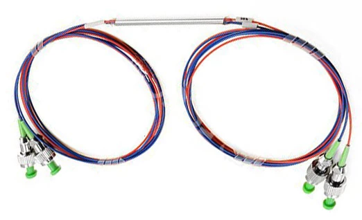
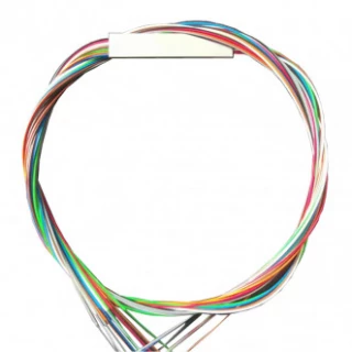
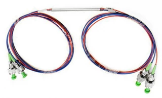
The Single-Mode Visible Light Fiber Coupler is a fused fiber optic splitter engineered for precision splitting and combining of visible-wavelength signals in demanding photonic systems. Covering the 400–700 nm spectral range, this coupler supports a comprehensive selection of popular visible laser wavelengths including 405 nm, 430 nm, 450 nm, 457 nm, 460 nm, 473 nm, 488 nm, 532 nm, 630 nm, 633 nm, 635 nm, and 650 nm, with additional custom wavelengths available upon request. By leveraging a high-quality single-mode fiber platform, the device delivers low insertion loss, low polarization dependent loss (PDL), and high stability, making it well suited for both laboratory and field applications where reliable visible-light signal distribution is critical.
Designed as a compact fused coupler, this splitter is available in standard 1×2 and 2×2 port configurations to support a wide variety of optical architectures. Typical applications include optical communication and data transmission at visible wavelengths, distributed fiber sensing, optical power monitoring and distribution, and seeding or feedback paths in fiber laser and fiber amplifier setups. The combination of tight process control and optimized fusion technology provides excellent uniformity across output ports and long-term reliability over an extended operating temperature range from −40 °C to +85 °C.
Multiple splitting ratios are supported to match different system requirements, from symmetric 50/50 power distribution to highly asymmetric configurations such as 99/1 for tap monitoring. Representative options include 50/50, 60/40, 70/30, 80/20, 90/10, 95/5, 98/2, and 99/1, with corresponding optimized insertion loss specifications for each ratio. This flexibility allows the coupler to be used as a main power splitter, as a sampling tap to monitor system performance, or as a low-loss distribution element in multi-branch optical networks operating in the visible regime.
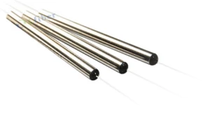
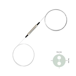
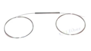
To support integration into different platforms, the Single-Mode Visible Light Fiber Coupler can be supplied with a variety of fiber and pigtail configurations. Options include 250 μm bare fiber for direct splicing in compact modules, 900 μm tight-buffered fiber for robust routing in instrumentation, and 2 mm or 3 mm jacketed cables for extra mechanical protection. The optical assembly is housed in a durable steel tube package (commonly Φ3.0 × 54 mm or Φ3.0 × 70 mm), with optional custom ABS box packaging available for cabled versions or multi-channel assemblies. Typical single-mode visible fibers such as 400-HP, 405-HP, 430-HP, 460-HP, S405-XP, SM450, SM600, SM650, and related types are supported to match specific wavelength ranges and mode-field requirements.
The coupler’s performance is specified without connectors to give a true indication of intrinsic device loss; when connectors are required, the additional insertion loss per mated connector pair is typically below 0.3 dB. Standard connector options such as LC/UPC, LC/APC, SC/UPC, SC/APC, FC/UPC, FC/APC, ST, MU, and others can be provided to align with existing system infrastructure. With its combination of low insertion loss, low PDL, and robust environmental stability, this single-mode visible-light fused fiber coupler offers a dependable solution for precision optical power management in research, medical, industrial, and communication systems that operate across the visible spectrum.
Single-Mode and Polarization-Maintaining Fiber Coupler (Visible Light Fiber Optic Splitter)
Specifications
| Port Configuration: | 1x2, or 2x2 |
|---|---|
| Connector: | None, LC/UPC, LC/APC, SC/UPC, SC/APC, FC/UPC, FC/APC, ST, MU, Custom … |
| Center Wavelength (nm): | 400~700nm (Optional), Typ. wavelengths of 405nm, 430nm, 450nm,457nm, 460nm, 473nm, 488nm, 532nm, 630nm, 633nm, 635nm, 650nm, Others on Request |
| Fiber Type: | Single-Mode (Non-PM) or Polarization-Maintaining (PM) Fibers |
| Split Ratio: | 50/50, 60/40, 70/30, 80/20, 90/10, 95/5, 98/2, 99/1, Custom … |
| Fiber Type: | 630-HP, 460-HP, 405-HP, 400-HP, S405-XP, SM450, SM600, SM650, Custom … |
Got questions about specs? Use the inquiry form to ask.
 Download Data Sheet

Features
- Wide Visible Wavelength Coverage (400–700 nm) – Optimized for single-mode operation across the full visible spectrum, including popular laser lines at 405, 430, 450, 457, 460, 473, 488, 532, 630, 633, 635, and 650 nm, with custom wavelengths available on request.
- High-Performance Single-Mode Fused Fiber Design – Precision fused biconical taper (FBT) technology ensures stable, repeatable splitting performance specifically engineered for visible light fiber optic systems.
- Low Insertion Loss – Typical insertion loss ≤3.8 dB for 50/50 split, with optimized values for other splitting ratios (e.g., ≤0.9 dB/13.0 dB for 90/10 and ≤0.4 dB/24.0 dB for 99/1), minimizing power loss in demanding optical setups.
- Excellent Split Ratio Options – Available in a wide range of fixed splitting ratios, including 50/50, 60/40, 70/30, 80/20, 90/10, 95/5, 98/2, 99/1, and fully customizable ratios for precise optical power management.
- Low Polarization Dependent Loss (PDL) – PDL ≤0.15 dB for reliable performance in polarization-sensitive applications such as interferometry, metrology, and precision sensing.
- High Uniformity Between Output Ports – Uniformity ≤1.0 dB helps ensure balanced power distribution across output channels, critical for multi-channel measurements and system calibration.
- 1×2 and 2×2 Port Configurations – Standard configurations meet the needs of both simple splitting/combining and more complex optical routing schemes in laboratory and OEM systems.
- Single-Mode Fiber Optimized for Visible Range – Uses specialized visible single-mode fibers (e.g., 400-HP, 405-HP, 430-HP, 460-HP, S405-XP, SM450, SM600, SM650, etc.) to ensure true single-mode propagation at short wavelengths.
- Compact and Robust Packaging – Offered in rugged steel tube packages (Φ3.0 × 54 mm or Φ3.0 × 70 mm) and custom ABS box modules for easy system integration and long-term reliability.
- Flexible Pigtail Options – Available with 250 μm bare fiber, 900 μm loose tube, or 2 mm / 3 mm jacketed cable, allowing direct integration into laboratory setups, field systems, or OEM equipment.
- Wide Operating Temperature Range – Designed for stable performance from -40 °C to +85 °C, suitable for both controlled lab environments and harsh industrial conditions.
- Connector Configuration Versatility – Can be supplied connectorized or unterminated; supports a full range of connector types such as FC/UPC, FC/APC, SC/UPC, SC/APC, LC/UPC, LC/APC, ST, MU, or custom terminations according to user requirements.
- Low Additional Loss with Connectors – Connector-induced insertion loss is typically <0.3 dB per connector pair, enabling plug-and-play use with minimal system penalty.
- Highly Reliable and Stable – Built to telecom and industrial-grade standards with strict process control, offering excellent long-term stability in optical power splitting and combining, even under thermal and mechanical stress.
- Ideal for Visible Optical Communication and Test Systems – Suited for short-reach visible optical communication links, R&D test benches, and optical alignment setups where visible wavelengths are preferred.
- Optimized for Fiber Sensors and Instrumentation – Excellent choice for fiber-optic sensors, interferometers, biomedical instruments, laser diagnostics, and spectroscopy, where low loss and low PDL are critical.
- Reliable Optical Power Distribution – Functions as a stable visible light power splitter/combiner for beam monitoring, reference channels, power tapping, and multi-point measurement architectures.
- Compatible with Fiber Amplifier and Laser Systems – Can be integrated in visible fiber amplifier setups and laser delivery systems for signal tapping, feedback control, and power sharing.
- Customizable Fiber Lengths – Standard pigtail lengths (e.g., 0.5 m, 1.0 m) and fully customizable lengths support both benchtop and rack-mounted configurations without additional splicing.
- OEM & Custom Engineering Support – Custom configurations available for wavelength, split ratio, fiber type, package format, pigtail protection, and connectivity, enabling tailored solutions for system integrators and instrument manufacturers.
Applications
- Visible Laser Power Splitting and Monitoring
Ideal for splitting and monitoring power from red, green, and blue single-mode diode lasers (405–650 nm) in R&D labs, laser manufacturing lines, and OEM laser subsystems. Enables stable sampling of output power for laser characterization and feedback control. - Single-Mode Visible Optical Communication Links
Used as a fused fiber splitter in short-reach visible free-space and fiber-based communication systems, including specialty links at 488 nm, 532 nm, 633 nm, and 650 nm where low insertion loss and low PDL are critical for signal integrity. - Fiber-Optic Test and Measurement Setups
Deployed in optical benches as a 1x2 or 2x2 visible coupler for distributing reference beams to power meters, optical spectrum analyzers, and photodetectors for calibration, stability monitoring, and insertion loss testing at visible wavelengths. - Interferometry and Coherent Optics
Functions as a beam splitter in single-mode fiber interferometers (Michelson, Mach–Zehnder, Sagnac) at visible wavelengths for precision metrology, surface profiling, and phase-sensitive measurements. - Fiber-Based Optical Sensing Systems
Serves as the core coupler in fiber sensor networks using visible light, such as strain, temperature, acoustic, vibration, pressure, and biochemical sensors, where low PDL and high stability maintain sensor accuracy and repeatability. - Distributed and Multipoint Fiber Sensor Arrays
Applied as a power distributor to feed multiple sensor heads along a single fiber line (e.g., FBG arrays or interferometric probes in the visible range) with configurable splitting ratios from 50/50 to 99/1. - Biomedical Imaging and Diagnostic Equipment
Integrates into fiber-delivered illumination paths for fluorescence imaging, confocal microscopy, OCT in the visible band, endoscopy, and dental/medical diagnostic devices to split or combine visible light between multiple channels. - Life Science and Laboratory Instrumentation
Utilized in spectroscopy systems, flow cytometers, cytometry analyzers, microfluidic devices, and DNA sequencers where visible lasers (e.g., 488 nm, 532 nm, 633 nm, 635 nm, 650 nm) must be split to multiple detection or excitation paths. - Industrial Alignment and Machine Vision Illumination
Used to split single-mode visible beams for multi-point alignment lights, vision-system illumination channels, position-sensing arrays, and precision machine tools needing stable, low-loss light distribution. - Laser Display and Projection Systems
Supports RGB laser projection and heads-up displays by routing or sampling visible laser power (blue, green, and red) in optical engines, projector modules, and color-combining assemblies for monitoring and balancing output. - Optical Power Distribution in Research Facilities
Employed in universities and research labs to distribute visible laser sources to multiple experimental stations, enabling shared use of stable, single-mode beams at different predefined splitting ratios. - Visible Fiber Amplifier and ASE Source Monitoring
Interfaces with visible-band fiber amplifiers or ASE sources as an optical tap coupler, allowing non-intrusive sampling of output power and spectrum for stabilization, gain monitoring, and safety interlocks. - Quantum Optics and Single-Photon Experiments
Suitable as a low-loss visible single-mode splitter in quantum optics setups that use 405 nm, 488 nm, 532 nm, 630–650 nm, or similar wavelengths for heralded photons, entanglement experiments, and single-photon detection chains. - Metrology and Precision Calibration Systems
Used to split stable reference lasers at visible wavelengths into measurement and reference arms for wavelength calibration, optical frequency standards, and long-term stability monitoring of metrology-grade sources. - Holography and Coherent Imaging
Acts as the fiber-based beam splitter in holographic recording and reconstruction setups, dividing coherent visible beams into object and reference paths for digital and optical holography. - Fiber-Coupled Spectroscopy and Colorimetry
Deployed in absorption, fluorescence, and Raman spectroscopy systems using visible light, routing source light to the sample and reference channels or combining multiple probe paths into a single detection fiber.
Frequently Asked Questions
What is a single-mode visible light fiber coupler and how is it used?
What wavelength range and split ratios are available for this visible fiber optic splitter?
What are the typical insertion loss and polarization dependent loss (PDL) for this coupler?
Which fiber types, pigtail diameters, and connector options are supported?
What is the operating temperature range and reliability of this visible fiber coupler?
How do I select the right splitting ratio for my visible laser or sensor application?
Can this single-mode visible coupler be customized, and what information should I provide when ordering?
Got more questions? Use the inquiry form to ask the supplier directly.
Similar Products
Your inquiry has been received.
Create an account by adding a password
Why create an account?
- Auto-complete inquiry forms
- View and manage all your past messages
- Save products to your favorites
- Close your account anytime — no hassle