
Description
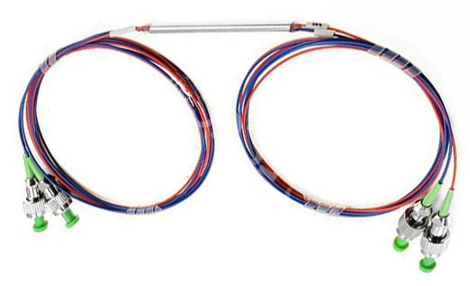
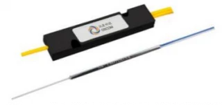
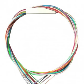
The visible/infrared single‑mode fiber optic coupler is a high‑performance passive component designed for precise splitting or combining of optical power across a very wide spectral range from 400 nm to 2000 nm. Engineered for low insertion loss, low polarization dependent loss (PDL), and long‑term stability, this coupler is ideal for demanding applications in optical communication systems, fiber sensing, optical measurement, and fiber laser or amplifier setups. Compared with conventional telecom‑only couplers, it extends operation deep into the visible and near‑infrared bands, making it particularly suitable for integrated systems that span multiple wavelengths or require wavelength‑flexible test and measurement capability.
Covering both common visible laser lines (such as 405, 430, 450, 473, 488, 532, 633, 635, and 650 nm) and popular infrared wavelengths (780, 830, 850, 980, 1064, 1480, 1570, 1625, 1700, 1950, and 2000 nm), this single‑mode coupler supports a broad selection of laser sources and detectors often used in spectroscopy, biomedical optics, free‑space optical links, and precision metrology. The device employs high‑grade single‑mode fibers, including telecom‑standard SMF‑28e and various high‑numerical‑aperture specialty fibers, to maintain excellent mode quality and stable performance over the entire specified bandwidth (typically ±10 nm around the center wavelength). This makes the coupler a robust, drop‑in solution for both lab‑grade and OEM systems.
Designed with versatility in mind, the coupler is available in both 1×2 and 2×2 port configurations and supports a comprehensive range of split ratios: 50/50, 60/40, 70/30, 80/20, 90/10, 95/5, 98/2, and 99/1. This allows system designers to precisely tailor power distribution between channels, whether for balanced signal splitting, tap monitoring, feedback loops, or power scaling in fiber lasers and amplifiers. Low insertion loss (down to sub‑dB levels at high‑asymmetry ratios) and tight uniformity are carefully controlled to ensure minimal signal degradation and consistent performance between output ports. The low PDL specification (as low as 0.1 dB for certain grades) is particularly valuable in polarization‑sensitive systems and in applications where signal integrity is critical.
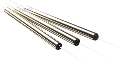
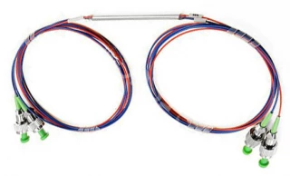
For practical deployment across diverse environments, the coupler is built in rugged steel tube or ABS box packages with multiple pigtail options. Users can select 250 μm bare fiber for compact integration, 900 μm loose tube for added mechanical protection, or 2 mm/3 mm jacketed cable for field‑ready installations. Standard steel tube housings (for example, φ3.0 × 54 mm or φ3.0 × 70 mm) provide excellent mechanical stability and ease of handling, while custom ABS box packages facilitate panel mounting and integration into instrument chassis or distribution modules. A wide variety of connector options, including LC, SC, FC, ST, MU, and others in UPC or APC polish, enable straightforward mating with existing fiber networks and test setups.
The coupler is specified for operation over a broad temperature range from −40 °C to +85 °C, ensuring reliable performance in both controlled laboratory environments and harsh industrial or outdoor installations. Each device is carefully manufactured and tested to meet strict insertion loss and PDL limits without connectors; when connectors are added, the incremental loss per connector pair is kept very low, typically less than 0.3 dB. With its combination of wide wavelength coverage, flexible configuration options, and robust environmental tolerance, this visible/infrared single‑mode fiber optic coupler provides a dependable, high‑value solution for modern optical communication, sensing, and photonics research applications.
Single-Mode (NOn-PM) or Polarization-Maintaining(PM) Fiber Optic Coupler for Infrared Light
Specifications
| Port Configuration: | 1x2, or 2x2 |
|---|---|
| Connector: | None, LC/UPC, LC/APC, SC/UPC, SC/APC, FC/UPC, FC/APC, ST, MU, Custom … |
| Center Wavelength (nm): | 780~2000nm (Optional), Typical Infrared Light of 780, 830, 850, 980, 1064, 1480, 1570, 1625, 1700, 1590, 2000 nm |
| Insertion Loss (dB): | ≤3.6 |
| Fiber Type: | Single-Mode (NOn-PM) or Polarization-Maintaining(PM) Fiber |
| Split Ratio: | 50/50, 60/40, 70/30, 80/20, 90/10, 95/5, 98/2, 99/1, Custom … |
Got questions about specs? Use the inquiry form to ask.
 Download Data Sheet

Features
- Broad Visible to Infrared Operating Range (400–2000 nm) – Single‑mode fiber optic coupler engineered for both visible (405–650 nm) and infrared (780–2000 nm) wavelengths, ideal for multi‑band laboratory, sensing, and telecom applications.
- Low Insertion Loss for High Optical Efficiency – Optimized design with typical insertion loss down to ≤3.4 dB for 50/50 splits at 780–2000 nm (Grade P) and ≤3.6 dB (Grade A), minimizing power budget penalties in demanding fiber optic networks.
- Ultra‑Low Polarization Dependent Loss (PDL) – PDL as low as ≤0.10–0.15 dB over the specified range, ensuring stable performance in polarization‑sensitive systems such as precision sensing, metrology, and coherent communication links.
- Multiple Port Configurations (1×2 and 2×2) – Flexible topology choices for splitting or combining optical signals, supporting common configurations used in coupler‑based splitters, interferometers, monitoring ports, and redundant signal paths.
- Wide Selection of Splitting Ratios – Standard and asymmetric split options including 50/50, 60/40, 70/30, 80/20, 90/10, 95/5, 98/2, 99/1, and custom ratios to match precise power distribution requirements in system design.
- High Uniformity Between Output Ports – Uniformity as low as ≤0.6 dB (typical Grade P at 780–2000 nm) ensures consistent power levels at each output, crucial for multi‑channel systems, balanced detection, and sensor arrays.
- High Reliability and Long‑Term Stability – Rugged internal structure and precision fusion tapering process deliver stable optical performance over time, meeting the reliability needs of industrial, telecom, and field‑deployed instrumentation.
- Wide Operating Temperature Range (−40 °C to +85 °C) – Designed for harsh environments, enabling stable coupling in outdoor, industrial, and aerospace systems where temperature variation is critical.
- Single‑Mode Fiber Design for Precise Signal Control – Utilizes high‑quality single‑mode fibers (e.g., SMF‑28e, HI780C, HI1060, 780‑HP, 630‑HP, 405‑HP, S405‑XP and others) to ensure low‑mode interference, low dispersion, and excellent beam quality.
- Optimized for Common Laser Wavelengths – Supports a comprehensive set of laser lines: 405, 430, 450, 457, 460, 473, 488, 532, 630, 633, 635, 650 nm (visible) and 780, 830, 850, 980, 1064, 1480, 1570, 1590, 1625, 1700, 2000 nm (infrared), ideal for diode, DPSS, fiber, and solid‑state lasers.
- Low Excess Loss Across Bandwidth – Tight bandwidth (±10 nm) around center wavelengths and low additional losses reduce overall system noise and maintain high signal‑to‑noise ratio in measurement and communication setups.
- Multiple Pigtail Options for Easy Integration – Available with 250 μm bare fiber, 900 μm loose tube, and 2 mm or 3 mm cable pigtails, accommodating direct splicing, connectorization, or rugged cabling as required.
- Compact and Robust Packaging – Offered in stainless steel tubes (Φ3.0 × 54 mm, Φ3.0 × 70 mm) and custom ABS box packages, suitable for tight‑space integration in instruments, rack systems, and optical modules.
- Connector and Fiber Length Customization – Supports standard fiber connectors including FC/UPC, FC/APC, SC/UPC, SC/APC, LC/UPC, LC/APC, ST, MU, or no connector, with customizable fiber lengths (e.g., 0.5 m, 1.0 m, or per order) for plug‑and‑play installation.
- High‑Grade Performance Options (P and A Grades) – P‑grade and A‑grade variants allow users to balance cost and performance, with lower insertion loss and tighter uniformity for critical‑performance optical networks.
- Ideal for Optical Communication Systems – Suited for CATV, FTTH, fiber backbone, and test‑bed networks where precise power splitting and low loss at C‑band and L‑band wavelengths are essential.
- Excellent for Fiber Sensing and Measurement – Low PDL and high stability make this coupler an excellent choice for interferometric fiber sensors, distributed sensing (DTS/DAS), and precision optical metrology.
- Effective Optical Power Distribution and Monitoring – Functions as a reliable optical power splitter/combiner for power tapping, feedback loops, and real‑time monitoring in laser systems and optical benches.
- Compatible with Fiber Amplifier Systems – Supports key pump and signal wavelengths (980 nm, 1480 nm, 1550–1570 nm, 1625 nm, 2000 nm), enabling integration in EDFA, YDFA, TDFA, and other fiber amplifier modules.
Applications
- Optical communication links in the visible and infrared bands
Ideal for splitting or combining signals in short- and long-haul fiber optic communication systems operating from 400 nm to 2000 nm, including access networks, metro networks, and backbone links. - Fiber laser systems and laser beam delivery
Used as power splitters and combiners in visible and IR fiber laser cavities, pump/signal routing, and beam delivery lines for wavelengths such as 405, 488, 532, 633, 650, 780, 850, 980, 1064, 1480, 1570, and 2000 nm. - Erbium-, ytterbium-, and thulium-doped fiber amplifiers
Suitable for use in EDFAs, YDFAs, and TDFAs as pump/signal combiners, monitoring ports, and gain-flattening/splitting elements due to low insertion loss and low PDL across 780–2000 nm. - Fiber optic sensing and distributed measurement
Employed in fiber Bragg grating (FBG) sensor networks, interferometric sensors, and distributed temperature/strain sensing (DTS/DSS) to split reference and sensing arms with high stability over -40 to +85 °C. - Interferometric systems (Mach–Zehnder, Michelson, Sagnac)
Acts as the key 1×2 or 2×2 splitting and combining element in precision interferometers for metrology, vibration analysis, and phase-sensitive measurements in both visible and infrared windows. - Optical coherence tomography (OCT)
Used to separate reference and sample arms and to recombine the interference signal in OCT systems operating at typical bands around 800 nm, 1060 nm, and 1300–1700 nm. - Biomedical and life-science instrumentation
Suitable for fluorescence excitation and collection, endoscopic illumination, confocal microscopy, and spectroscopy setups where stable power splitting at wavelengths like 405, 488, 532, 633, 650, 780, and 850 nm is required. - Optical power distribution and tapping
Used as 50/50 or non-50/50 splitters (60/40 to 99/1) for distributing laser or LED power to multiple channels, or for tapping off a small percentage (1–10%) of power for real-time monitoring and control. - Wavelength-agnostic test and measurement setups
Convenient for general-purpose laboratory test benches, optical alignment, source comparison, and detector calibration where a broadband visible/IR coupler simplifies setup across 400–2000 nm. - Laser diode and superluminescent diode (SLD) source monitoring
Enables power feedback loops and lifetime testing by routing a small fraction of the output (e.g., 95/5, 98/2, 99/1) to a monitoring photodiode while preserving the majority of power for the application. - Quantum optics and single-photon experiments
Appropriate for splitting and combining single-photon or weak coherent states at common quantum wavelengths (405, 450, 532, 633, 780, 830, 850 nm) in quantum key distribution (QKD), entanglement, and interference experiments. - Spectroscopy and metrology
Used in absorption, reflection, and fluorescence spectroscopy to route light to samples and reference channels, as well as in wavelength calibration and frequency-stabilized laser systems. - Industrial and manufacturing process monitoring
Deployed in inline inspection, position sensing, strain and vibration monitoring, and machine-vision illumination schemes where robust fiber couplers withstand wide temperature ranges. - Harsh-environment and outdoor optical networks
Suitable for remote sensing, oil & gas exploration, structural health monitoring, and field-deployed communication links thanks to high reliability, low loss, and -40 ~ +85 °C operating temperature. - Research and development in photonics
A flexible building block for laboratory setups in universities and R&D centers working on new devices, modulation formats, nonlinear fiber optics, and prototype optical systems in both visible and IR ranges. - Education and training in fiber optics
Well-suited for teaching labs that demonstrate principles of interference, splitting ratios, loss, and polarization effects over a broad spectral range using standard single-mode fibers.
Frequently Asked Questions
What is a visible/infrared single‑mode fiber optic coupler and how is it used?
Which wavelengths and fiber types are supported by this fiber optic coupler?
What splitting ratios and insertion loss values are available?
What are Grade P and Grade A in this coupler’s specifications, and how do they affect performance?
What connector, pigtail, and package options are available for this fiber optic coupler?
Can this visible/IR single‑mode coupler be customized for my specific application?
What is the operating temperature range and long‑term reliability of this coupler?
Got more questions? Use the inquiry form to ask the supplier directly.
Similar Products
Your inquiry has been received.
Create an account by adding a password
Why create an account?
- Auto-complete inquiry forms
- View and manage all your past messages
- Save products to your favorites
- Close your account anytime — no hassle