
Waveform Generators and Analyzers for Light Analysis
Frequently Asked Questions
What are waveform generators and analyzers in the context of photonics and light analysis?
In photonics, waveform generators and analyzers are electronic instruments used to create and characterize electrical drive signals that modulate optical sources, detectors, or modulators. Generators output well-defined analog or digital waveforms (sine, pulse, arbitrary shapes), while analyzers capture and decompose signals in the time and frequency domains to evaluate modulation formats, jitter, noise, and distortion impacting optical systems.
How does an arbitrary waveform generator (AWG) work and why is it important for optical experiments?
An AWG uses digital-to-analog converters (DACs) and high-speed memory to synthesize user-defined waveforms with precise amplitude, phase, and timing control at sampling rates that can exceed tens of GS/s. In optical R&D it is used to drive electro‑optic modulators, lasers, and RF components with complex modulation formats (QAM, OFDM, PAM‑4), enabling realistic testing of high‑speed optical communication links and advanced sensing schemes.
What types of waveform analyzers are commonly used with photonic systems and how do they differ?
Common analyzers include real‑time oscilloscopes, sampling oscilloscopes, vector signal analyzers (VSAs), and optical modulation analyzers (OMAs). Real‑time scopes capture long signal records for transient analysis, sampling scopes provide very high bandwidth for repetitive signals, VSAs perform IQ demodulation and vector error analysis of RF/modulated signals, and OMAs combine a coherent optical front‑end with digital signal processing to reconstruct amplitude and phase of complex optical waveforms.
Which key specifications should I look at when selecting a waveform generator for driving optical components?
Critical parameters include analog bandwidth, maximum sampling rate, vertical resolution (bits), output amplitude range, rise/fall time, and timing jitter. For high‑speed modulators, you typically need bandwidth and sampling rates well above the optical symbol rate, sub‑picosecond jitter, and output voltage swing compatible with the modulator’s Vπ and impedance (often 50 Ω).
What are the most important parameters when comparing waveform analyzers for high‑speed optical or RF testing?
Important metrics include analog bandwidth, sample rate, effective number of bits (ENOB), noise floor, trigger capabilities, and memory depth for long captures. For complex modulation analysis, also compare available demodulation options (e.g., QPSK, 16QAM, OFDM), supported symbol rates, clock recovery performance, and built‑in metrics such as EVM, BER estimates, eye diagrams, and constellation plots.
How do lead times, customization options, and main pricing drivers typically look for waveform generators and analyzers?
Lead times for standard benchtop units are often 2–8 weeks, while customized configurations (special interfaces, extended memory, tailored firmware options) can extend delivery to several months. Pricing is primarily driven by bandwidth, sampling rate, channel count, vertical resolution, analysis options/software licenses, and the inclusion of optical front‑ends or coherent receiver modules for direct optical waveform analysis.
Overview of Waveform Generators and Analyzers
Waveform Generators and Analyzers in the light analysis domain are electronic instruments used to drive and characterize optical modulators, detectors, and related photonic components. They provide controlled electrical drive signals and measurement capability for evaluating modulation formats, linearity, extinction ratio, and overall system performance in fiber-optic and free-space links.
On FindLight, Waveform Generators and Analyzers are oriented toward applications where accurate amplitude and phase control of electrical drive signals is required, including coherent transmission experiments, LiDAR modulation, high-speed test benches, and analog photonic links.
Modulator Bias Controllers
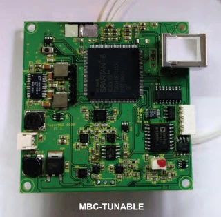
The primary sub-type in this category is modulator bias controllers. These are feedback-controlled units designed to maintain the optimal operating point of electro-optic (EO) modulators such as Mach-Zehnder, IQ, and phase modulators. Because EO modulators are sensitive to temperature drifts and device aging, manual biasing quickly becomes unstable in precision systems.
Modulator bias controllers within the broader family of Waveform Generators and Analyzers typically offer:
- Support for multiple modulation formats (intensity, phase, and I/Q)
- Automatic locking to key bias points (quadrature, null, maximum, or custom setpoints)
- Integrated dither or pilot tones with synchronous detection for bias feedback
- Compatibility with a range of photodiode monitor inputs (on-chip or external)
- Analog and digital control interfaces (front panel, USB, Ethernet, GPIB, or analog I/O)
Key Specifications to Compare
When evaluating Waveform Generators and Analyzers focused on modulator bias control, procurement engineers and R&D scientists should compare:
- Supported modulator type: single-ended vs. push-pull, LiNbO3, InP, silicon photonics, or polymer devices.
- Bias operating modes: number of controllable channels, quadrature vs. null tracking, and user-defined bias points.
- Control bandwidth and tracking speed: ability to follow thermal drifts and slow environmental changes without oscillation.
- Input wavelength and power range: photodiode responsivity range, allowable optical power, and linear operating region.
- Electrical interfaces: maximum bias voltage, output compliance range, and noise characteristics.
- Integration options: remote programmability, SCPI commands, trigger I/O, and compatibility with existing lab control software.
Using FindLight to Source Instruments
Browse the available Waveform Generators and Analyzers on FindLight to locate modulator bias controllers that match your system topology and performance targets. Review detailed datasheets, compare specifications across manufacturers, and shortlist units by channel count, voltage range, control bandwidth, and interface requirements.
You can contact suppliers directly from each product page to request technical clarifications, pricing, and lead times. Quote requests do not require registration, enabling rapid iteration during design, prototyping, and procurement planning.