


Description
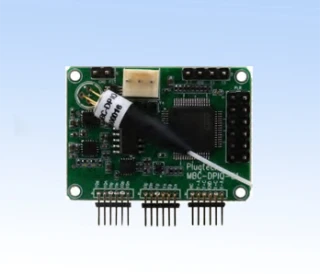
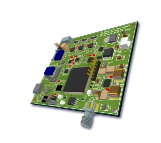
The MBC‑CHIP is a compact, single‑function modulator bias controller engineered for precise control of LiNbO3 and other electro‑optic Mach–Zehnder (MZ) modulators in demanding digital and analog photonic systems. Unlike bulky bench‑top controllers, this board‑level solution offers robust, long‑term bias stability in an ultra‑small footprint of only 1.8 × 0.8 × 0.5 inches, making it particularly suitable for OEM integration, space‑constrained instruments, and field‑deployed subsystems. By maintaining the optimal operating point of the modulator, the MBC‑CHIP improves signal integrity, minimizes drift, and enhances overall system performance for applications such as high‑speed fiber‑optic communications, test and measurement, and coherent or intensity‑modulated transmission links.
This controller is designed to automatically lock the working point of an MZ modulator at one of four key positions on its transfer function: positive‑slope quadrature (Quad+), negative‑slope quadrature (Quad‑), null, or peak. These operating points are critical in modern optical systems—quadrature operation supports linear modulation and complex modulation formats, while null and peak biasing are ideal for on–off keying and extinction‑ratio‑sensitive links. To ensure optimal performance from the outset, the desired locking mode is specified at the time of order, allowing the board to be delivered preconfigured for the target application and eliminating the need for complicated configuration in the field.
The MBC‑CHIP employs a low‑frequency pilot tone method to track and compensate slow drifts in the modulator transfer function. A small pilot tone, typically around 9.8 kHz and with an adjustable amplitude up to 300 mV, is superimposed on the DC bias. The corresponding modulation of the optical output is detected by a photodiode and analyzed by the controller, which then adjusts the bias voltage in real‑time to maintain the selected operating point within a tight locking accuracy of approximately 1–3 degrees. This closed‑loop control approach is well established in advanced optical communication systems and has been widely adopted for its reliability and ability to preserve optimal modulator performance over time, temperature, and component aging.
To facilitate easy integration into a wide range of optical architectures, the MBC‑CHIP is compatible with both built‑in and external photodiodes. In many LiNbO3 modulators, an internal monitor photodiode is provided, and the MBC‑CHIP can directly utilize this signal. For systems that require external monitoring, the controller supports a pigtailed photodiode option that can be soldered directly to the board, or the user can connect their own detector. With an input signal current range from approximately 0.8 µA to 80 µA, the board accommodates typical monitor diode outputs across a wide span of optical powers, making it suitable for both laboratory‑grade setups and more compact, power‑constrained modules.
The bias control output of the MBC‑CHIP provides a DC bias voltage spanning roughly −10 V to +10 V, adequate for driving the bias port of most standard MZ modulators used in telecom C‑band and related windows. A dedicated VC control line is also available over the same approximate range to support additional biasing or fine‑tuning requirements as needed by the system designer. By maintaining the modulator at the chosen operating point, the controller helps suppress waveform distortion, improve linearity in analog links, and maintain consistent extinction ratio or optical carrier suppression in digital and coherent systems.
System designers benefit from the straightforward electrical interface and modest power requirements. The MBC‑CHIP operates from symmetric power rails, typically +12 V and −12 V (within a ±10 V to ±15 V range), with a typical current consumption on the order of 20 mA per rail. This low power draw simplifies power‑supply design and makes the unit attractive for multi‑channel or high‑density line cards where many modulators must be controlled simultaneously. The operating temperature range of 0 °C to 70 °C supports deployment in controlled environments such as central offices, labs, and equipment racks, while storage temperatures from −40 °C to 80 °C protect the unit during transportation and handling.
From an integration standpoint, the small form factor and chip‑size layout are optimized for embedding into OEM equipment. The board can be mounted close to the modulator to minimize parasitic effects and cabling complexity, improving noise performance and response stability. This is especially important in high‑speed transmission systems and precision test setups, where maintaining clean RF and DC paths is crucial. The ability to order the MBC‑CHIP with or without a pigtailed photodiode, as well as with a choice
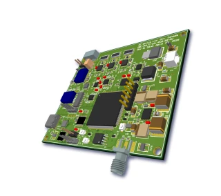
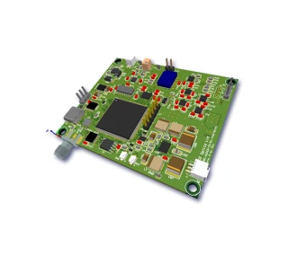
Chip Size Modulator Bias Controller
Specifications
| Product Type: | MBC |
|---|---|
| Modulation Type: | Other |
| Locking Slope: | Positive, Negative |
| Locking Mode: | Quad+, Quad-, Null, Peak Positions |
| Photodetector Type: | External |
| Tunability: | Unspecified |
| Input Signal Current: | 0.8–80 μA |
| Locking Accuracy: | 1–3 degree |
| DC Bias Voltage: | -10 to +10 V |
| Pilot Tone Frequency: | 9.8 kHz |
| Pilot Tone Amplitude Range: | 0–300 mV |
| VC DC Voltage: | -10 to +10 V |
| Positive Power Supply: | 10 to +15 V (typ. 12 V) |
| Negative Power Supply: | -15 to -10 V (typ. -12 V) |
| Positive Supply Current: | 20 mA |
| Negative Supply Current: | 20 mA |
| Operating Temperature: | 0 to 70 °C |
| Storage Temperature: | -40 to 80 °C |
| Dimensions (L X W X H): | 1.8 x 0.8 x 0.5 inch |
Got questions about specs? Use the inquiry form to ask.
 Download Data Sheet

Features
- Ultra-Compact Chip-Size Design – Low-profile footprint of only 1.8″ x 0.8″ x 0.5″ enables seamless integration into dense OEM optical modules and high-channel-count systems.
- Single-Function, Factory-Configured Bias Control – Optimized for a dedicated operating point to maximize stability and simplify system design, with four selectable modes:
- Quad+ – Positive-slope quadrature locking
- Quad- – Negative-slope quadrature locking
- Null – Minimum transmission bias point
- Peak – Maximum transmission bias point
- High-Precision Modulator Bias Locking – Typical locking accuracy of ±3° (as tight as 1°) ensures stable operation at the desired working point of Mach–Zehnder modulators, minimizing drift due to temperature and aging.
- Wide DC Bias Control Range – Supports DC bias voltages from -10 V to +10 V, compatible with a broad range of LiNbO3 and other electro‑optic modulators used in digital and analog communication systems.
- Integrated Pilot Tone Technique – Uses a built-in pilot tone at 9.8 kHz with an adjustable amplitude range of 0–300 mV (manually adjustable), providing robust automatic bias control even in the presence of signal modulation.
- Supports Built‑In or External Photodiode – Designed to work with the modulator’s internal photodiode or an external pigtailed photodiode that can be soldered directly to the board for maximum flexibility in monitoring configurations.
- Flexible Photodiode Options – Available with or without an integrated pigtailed PD:
- PD – Pigtailed photodiode included
- 00 – No pigtailed photodiode included
- Versatile Fiber Connector Choices – Multiple connector configurations to match common lab and OEM setups:
- FC/UPC (3U), FC/APC (3A)
- SC/UPC (SCU), SC/APC (SCA)
- LC/UPC (LCU), LC/APC (LCA)
- Dual Power Supply Operation – Operates from symmetric supply rails of +10 to +15 V and -10 to -15 V, with typical current consumption of only 20 mA per rail, making it suitable for low-power and portable systems.
- External Control Voltage Input – VC DC voltage range of -10 V to +10 V allows system-level adjustment, tuning, or override of the bias control, enabling closed-loop integration with higher-level controllers.
- Designed for Digital System Applications – Optimized specifically for digital optical transmission, coherent communication, and high-speed intensity modulation where stable quadrature or null/peak operation is critical to minimize bit errors and optimize extinction ratio.
- Stable Performance Over Broad Temperature Range – Specified operating range of 0 °C to +70 °C and storage from -40 °C to +80 °C ensures reliable bias control in lab, field, and OEM environments.
- Easy OEM Integration – Chip-size PCB layout with accessible solder pads for PD, power, and control signals simplifies integration into transceivers, test instruments, and custom optical subsystems.
- Compatible With Typical MZ Modulator Configurations – Reference configurations available for:
- Null/Peak applications where minimum or maximum output intensity is required
- Quadrature applications for linear modulation around the most sensitive operating point
- Improved System Stability and Signal Quality – Continuous bias tracking reduces drift and manual re-adjustment, enhancing long-term stability, maintaining modulation depth, and improving overall signal-to-noise and signal fidelity.
- Ideal for High-Speed RF/Optical Links – Well-suited for microwave photonics, analog optical links, coherent systems, and high‑bit‑rate digital communications where precise MZ modulator bias control is essential.
Applications
- Automatic Bias Control of LiNbO3 Mach–Zehnder Modulators
Maintains the operating point of lithium niobate MZ modulators at Quad+, Quad−, Null, or Peak, ensuring stable modulation depth and extinction ratio in high‑speed digital optical links. - Digital Coherent Optical Communication Systems
Used in coherent transmitters to lock the I/Q Mach–Zehnder modulators at precise quadrature points, improving constellation fidelity and minimizing phase and amplitude errors in advanced modulation formats (QPSK, 16QAM, 64QAM). - Optical Transmitters for NRZ, PAM‑4, and High‑Speed Serial Data
Provides bias stabilization in high‑data‑rate intensity‑modulated transmitters, reducing pattern‑dependent distortion and penalty in 10G, 25G, 40G, 100G+ fiber‑optic links. - Test and Measurement of External Modulators
Integrated into benchtop or rack‑mount test setups to keep the modulator at a fixed operating point during eye‑diagram, BER, and jitter measurements, enabling repeatable characterization of optical components and subsystems. - Optical Arbitrary Waveform Generation and Pulse Shaping
Ensures stable quadrature bias in systems that rely on precise phase and amplitude control for optical waveform synthesis, spectral shaping, and time‑domain pulse engineering. - Analog RF‑over‑Fiber and Microwave Photonics Links
Locks the modulator at quadrature to maximize linearity and spurious‑free dynamic range (SFDR) in analog photonic links transporting RF and microwave signals over optical fiber. - Optical Phase and Amplitude Modulation Experiments
Supports laboratory setups where precise control of the MZ transfer function is needed for phase modulation, amplitude modulation, and mixed‑mode experiments in photonics research. - Stabilization of Null and Peak Operating Points
Maintains deep extinction (Null) or maximum transmission (Peak) for on/off keying systems, optical shutters, and experiments requiring high contrast ratios. - Integrated OEM Optical Transmitter Modules
Embedded as a compact, chip‑size controller inside OEM transmitter subassemblies to provide long‑term bias stability without increasing system footprint. - Fiber‑Optic Sensing Interrogators
Used in interferometric and phase‑modulated fiber sensors to bias Mach–Zehnder modulators at optimal points for precise detection of strain, temperature, pressure, or acoustic signals. - Optical Signal Processing and Switching
Stabilizes MZ modulators used as optical switches, logic gates, or intensity processors in reconfigurable optical networks and photonic signal‑processing platforms. - Quantum Optics and Photonic Quantum Computing Setups
Maintains stable interferometric conditions in MZ modulators used for state preparation, amplitude control, and fast optical routing in quantum communication and quantum photonics experiments. - Optical Code‑Division Multiple Access (OCDMA) and Spread‑Spectrum Systems
Keeps modulators at defined bias points in systems that require precise control of encoded optical waveforms to minimize cross‑talk and maintain code orthogonality. - Laser Intensity Stabilization and Power Control
Works with an MZ modulator and internal or external photodiode to stabilize CW laser output intensity against temperature drift and aging, improving long‑term system reliability. - Photonic Integrated Circuit (PIC) Evaluation and Prototyping
Provides compact bias control for discrete or integrated MZ modulators on photonic chips, ideal for PIC prototyping, characterization, and small‑form‑factor assemblies. - Environmental and Long‑Term Drift Compensation
Compensates for temperature and aging drifts in LiNbO3 modulators, ensuring consistent performance in field‑deployed systems such as telecom, datacom, and defense links. - OEM Bias Control for Custom Modulator Packages
Serves as an embedded bias engine for custom‑packaged modulators where built‑in control electronics are not present, leveraging either the modulator’s internal photodiode or an external pigtailed PD. - R&D and Educational Photonics Laboratories
Simplifies experiments with Mach–Zehnder modulators for students and researchers by eliminating the need for continuous manual bias tuning when demonstrating transfer functions and modulation formats. - High‑Reliability Defense and Aerospace Photonics
Used in rugged optical communication and RF‑over‑fiber links where stable modulator bias is essential under wide environmental variations and mission‑critical conditions. - Optical Metrolo
Frequently Asked Questions
What is the MBC-CHIP Modulator Bias Controller and what does it do?
Which locking modes are available (Quad+, Quad−, Null, Peak) and how do I choose the right one?
How do I power and connect the MBC-CHIP in my optical modulation setup?
Can I use the MBC-CHIP with an external photodiode and what are the pigtailed PD options?
What are the key electrical and performance specifications of the MBC-CHIP?
What are the size and environmental operating conditions of the MBC-CHIP?
How is the MBC-CHIP ordered and what does the part number MBC-CHIP-PP-X-L mean?
Got more questions? Use the inquiry form to ask the supplier directly.
Similar Products


Your inquiry has been received.
Create an account by adding a password
Why create an account?
- Auto-complete inquiry forms
- View and manage all your past messages
- Save products to your favorites
- Close your account anytime — no hassle