

Description
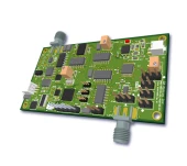
Modulator Bias Controller – MINI-SIL (DTS0215) – Compact OEM Bias Control for LN and Silicon Photonic Modulators
The MINI-SIL Modulator Bias Controller (MBC) is a compact, full‑function OEM solution engineered to stabilize and optimize the operating point of single LiNbO3 Mach–Zehnder (MZ) modulators and silicon-based electro‑optic modulators. In high‑speed optical communication, coherent systems, and test and measurement environments, even minor bias drifts can severely degrade extinction ratio, linearity, and overall link performance. This controller is designed specifically to counteract those effects by actively locking the modulator bias to the desired operating point and maintaining stable performance over time, temperature, and optical power fluctuations.
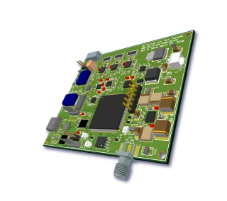
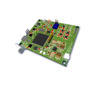
Covering an optical wavelength range from 1000 nm to 1650 nm and accepting detector input power levels from –30 dBm to –10 dBm, the MINI-SIL MBC integrates seamlessly into a wide variety of fiber‑optic setups. It is well suited for applications such as analog RF over fiber, broadband optical links, laboratory research, interferometric sensing, and silicon photonics prototyping. The low‑profile PCB form factor (approximately 1.6 × 3 × 0.65 inches) makes it easy to embed the controller directly into OEM modules, transceiver subassemblies, and benchtop instruments where PCB real estate is at a premium.
The controller is designed to lock the modulator’s operating point at several key positions on the Mach–Zehnder transfer curve, including positive-slope quadrature (Quad+), negative-slope quadrature (Quad–), minimum transmission (Null), and maximum transmission (Peak). These locking points are selectable via onboard jumpers, allowing the user to choose the optimal bias point for linear modulation, maximum extinction, or specific system-level performance goals. In null mode, the controller supports a typical extinction ratio up to 40 dB, making it particularly attractive for systems requiring deep suppression of the optical carrier or high contrast in on–off keyed modulation formats.
To support both traditional LiNbO3 modulators and modern silicon photonic devices, the MINI-SIL MBC provides a generous bias port range and drive capability. The bias voltage can be adjusted from –10 V to +10 V, and the bias current can be configured up to 250 mA, which is often required for silicon-based phase shifters and depletion-type modulators. This flexibility simplifies integration across different modulator technologies and ensures that one compact controller can serve multiple platforms without the need for external high‑current drivers.
The instrument incorporates a pilot tone based feedback technique to achieve automatic bias control. For quadrature locking, a small modulation depth in the 1–2% range is applied at a typical pilot tone frequency of 1 kHz, allowing the system to sense deviations from the desired operating point and correct them in real time. When operating in null mode, a lower modulation depth (down to about 0.1%) and a higher pilot tone frequency around 2 kHz are employed to minimize impact on the main data signal while maintaining precise control over the extinction level. This architecture is consistent with advanced bias controllers used in high‑end telecom and RF photonics systems, which rely on pilot tones to ensure long‑term, drift‑free performance.
Two primary operating modes are provided: calibration mode and locking mode. In calibration mode, the user can scan and identify the modulator’s transfer function characteristics, determine optimum bias points, and set up the slope and mode before engaging closed‑loop operation. Once the system is characterized, locking mode maintains the selected operating point automatically. A dedicated calibration‑off state enables quick system setup when the controller is already configured for the desired modulator, reducing commissioning time and simplifying repeated deployments in production environments and test setups.
The MINI-SIL MBC is designed as a stand‑alone controller that does not require a computer interface for standard operation, which is particularly beneficial in OEM and embedded contexts where simplicity and reliability are paramount. Locking slope (positive or negative) and operating mode (Quad+, Quad–, Null, or Peak) are user‑selectable using jumpers, eliminating the need for software drivers or digital control lines. This approach reduces integration complexity and ensures predictable behavior once the controller is installed and configured.
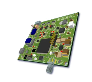
OZ Optics MBC MINI SIL Modulator Bias Controller for LN Silicon Modulators
Specifications
| Product Type: | MBC, MBC-MINI |
|---|---|
| Modulation Type: | Other |
| Detector Input Power: | -30 dBm |
| Locking Slope: | Positive, Negative |
| Locking Mode: | Quad+, Quad-, Null, Peak Positions |
| Photodetector Type: | External |
| Tunability: | Tunable |
| Positive Power Voltage: | 11.5 to 12.5 V |
| Profile Height: | 0.65 inch |
| PCB Board Size: | 1.6 x 3 x 0.65 inch |
| Bias Port Voltage Range: | -10 to +10 V |
| Bias Port Current Capability: | up to 250 mA |
| Weight: | 0.2 lb |
| Dimensions: | 1.6 x 3 x 0.65 inch |
| Storage Temperature: | -40 to 85 °C |
| Operating Temperature: | 0 to 70 °C |
| Negative Power Current: | 40 mA |
| Positive Power Current: | 60 mA |
| Negative Power Voltage: | -12.5 to -11.5 V |
| Detector Input Power: | -30 to -10 dBm |
| Pilot Tone Frequency (NULL): | 2000 Hz |
| Pilot Tone Frequency (QUAD): | 1000 Hz |
| Modulation Depth (Null): | 0.1 % |
| Modulation Depth (QUAD): | 1 to 2 % |
| Locking Mode: | Quad+ (Quad-) or Null (Peak) |
| Locking Slope: | Positive or Negative |
| Null Mode Extinction Ratio: | 25 to 40 dB |
| Bias Current: | 5 to 250 mA |
| Bias Voltage: | -10 to +10 V |
| Optical Wavelength: | 1000–1650 nm |
Got questions about specs? Use the inquiry form to ask.
 Download Data Sheet

Features
- Optimized for Single LN and Silicon Modulators – Specifically designed for both single Lithium Niobate Mach-Zehnder (MZ) modulators and silicon-based optical modulators, making it ideal for general-purpose single‑modulator bias control in high‑speed photonic systems.
- Flexible Locking Slope Selection (QUAD+ / QUAD- / NULL / PEAK) – User-selectable locking slopes allow you to lock the modulator bias at positive or negative quadrature (Quad+ / Quad−), or at Null / Peak operating points to meet a wide variety of modulation formats and link optimization strategies.
- User-Selectable Locking Modes via Jumpers – Simple on-board jumper configuration lets you select between Quad+/Quad− and Null/Peak locking modes without the need for firmware changes, software control, or external configuration tools.
- High-Current Bias Port up to 250 mA – Integrated bias output can deliver up to 250 mA of current, supporting demanding silicon modulators that require higher drive current; current limit can be factory-configured on request for additional safety and optimization.
- Wide Programmable Bias Voltage Range (−10 V to +10 V) – Bias port provides a broad voltage swing from −10 V to +10 V, enabling precise setting of the modulator operating point across a wide range of device characteristics and process variations.
- Integrated RF Gating Capability – RF gating input allows enabling or disabling RF drive based on system conditions, improving link performance in burst-mode or time-division-multiplexed applications.
- Pilot Tone Gating and Pilot Tone Control – Built-in pilot tone generation and gating provide robust automatic bias control with selectable pilot tone frequencies for quadrature and null operation, enabling stable long‑term locking without external tone generators.
- Two Distinct Operation Modes: Calibration & Locking – Dedicated calibration mode simplifies initial setup and identification of operating points, while locking mode maintains the desired bias point during normal operation for stable, drift‑free performance.
- “Calibration Off” Mode for Fast System Setup – A calibration-off function allows users to bypass calibration when needed and quickly transition into locking mode, accelerating system startup and reducing integration time.
- High Extinction Ratio in Null Mode – Designed to achieve a typical null mode extinction ratio up to 40 dB (≥ 25 dB minimum), supporting high-contrast on/off keying and low residual optical carrier applications.
- Wide Optical Wavelength Compatibility (1000–1650 nm) – Operates over a broad wavelength range from 1000 nm to 1650 nm, covering O-, C-, and L-band telecom windows, as well as many datacom and sensing wavelengths.
- High-Sensitivity Photodetector Interface – Optimized for detector input powers from −30 dBm to −10 dBm, ensuring reliable bias control even at low tapped power levels.
- Included Pigtailed Photodetector – A pigtailed photodiode is supplied for immediate use, enabling straightforward implementation of the recommended configuration with a small optical coupler at the modulator output.
- Support for External Photodetectors – External photodiode access is provided, allowing users to connect their own detectors (e.g., integrated in an existing receiver chain or custom monitoring tap) for maximum layout flexibility.
- Compact Low-Profile OEM Form Factor – Very small PCB footprint of approximately 1.6" × 3" × 0.65" (low profile 0.65") and light weight (~0.2 lb) makes it ideal for dense OEM integration, benchtop modules, or embedded telecom/datacom equipment.
- Standalone Hardware – No PC Required – Fully standalone operation; all configuration is done via hardware jumpers and connections, eliminating the need for a computer interface, software drivers, or complex digital control electronics.
- Dual Supply Operation (+12 V / −12 V) – Uses standard ±12 V supply rails (+11.5 to +12.5 V and −12.5 to −11.5 V), with typical current draws around 60 mA (positive) and 40 mA (negative), simplifying power integration in existing photonic platforms.
- Stable Performance Over Wide Temperature Range – Designed for reliable operation from 0 °C to +70 °C with storage down to −40 °C and up to +85 °C, suited for lab, industrial, and telecom environments.
Applications
- Stabilization of Lithium Niobate (LN) Mach–Zehnder Modulators
Maintains a fixed operating point (Quad+, Quad–, Null, or Peak) for single LN MZ modulators in high‑speed optical links, ensuring stable modulation depth and minimal drift over time. - Silicon Photonics Modulator Bias Control
Provides up to 250 mA drive current and ±10 V bias range required by many silicon-based modulators for reliable operation in integrated photonics transceivers and test platforms. - Coherent Optical Communication Systems
Used to lock IQ and phase modulators at quadrature in coherent transmitters, improving constellation stability, phase accuracy, and long‑term system performance in 100G/400G/800G links. - High-Speed Digital Intensity Modulation Links
Maintains the optimum operating point of intensity modulators in NRZ, PAM4, and advanced modulation format systems to reduce eye closure, improve BER, and enhance link margin. - Analog Fiber Optic Links and RF-over-Fiber
Biases Mach–Zehnder modulators in their most linear region for CATV distribution, antenna remoting, and RF-over-fiber applications, maximizing SFDR and minimizing intermodulation distortion. - Microwave Photonics and Phase-Modulated Systems
Supports precise control of bias for modulators used in microwave photonic filters, frequency up‑conversion, and phase-modulated links where bias drift can severely degrade RF performance. - Optical Signal Generation for Test & Measurement
Provides a stable bias point for modulators used to generate calibrated optical waveforms, pulse trains, and optical carriers in optical component and subsystem test setups. - Quantum Optics and Quantum Communication Experiments
Stabilizes interferometric modulators used in quantum key distribution (QKD), entangled photon experiments, and single‑photon interferometry where path‑length and bias drift must be minimized. - Interferometric Sensor Systems
Used to bias interferometric modulators and phase shifters in fiber optic gyroscopes, hydrophones, strain and temperature sensors, ensuring operation at optimal quadrature points for maximum sensitivity. - Optical Coherence Tomography (OCT) and Interferometry
Stabilizes bias in modulators employed for phase shifting and fringe control in OCT and other interferometric imaging or metrology systems, improving resolution and measurement repeatability. - Integrated Photonic Circuit Characterization
Provides compact bias control for on‑chip silicon or LN modulators during wafer‑level and packaged device characterization, enabling reproducible measurements and automated testing. - Optical Lab Benchtop Experiments and Prototyping
Serves as a stand‑alone, computer‑independent bias controller in R&D laboratories for quick setup of LN and silicon modulators in prototypes, feasibility studies, and educational experiments. - Long-Term Stability in Environmental and Thermal Cycling Tests
Maintains the desired operating point of modulators subjected to temperature variations, vibration, or extended burn‑in tests, allowing accurate evaluation of device reliability and drift characteristics. - Pulse Shaping and Optical Arbitrary Waveform Generation
Keeps amplitude and phase modulators at their calibrated bias points in multi‑stage pulse shaping systems to ensure repeatable temporal and spectral profiles for ultrafast optics applications. - Optical Switching and Reconfigurable Photonic Networks
Stabilizes modulators and phase shifters used as optical switches or variable attenuators in reconfigurable optical add‑drop multiplexers (ROADMs) and photonic integrated switching fabrics. - Bias Control in Dual-Parallel MZ (DPMZM) Structures
Provides precise biasing for single modulators within DPMZM architectures used for carrier-suppressed, single-sideband, or advanced modulation format generation in microwave photonics and communications. - Educational and Training Kits in Photonics
Integrates into university and training setups to demonstrate bias dependence of Mach–Zehnder modulators, extinction ratio optimization, and quadrature locking techniques without requiring a PC. - OEM Integration into Compact Optical Transmitters
Low-profile PCB design (1.6" x 3" x 0.65") enables easy integration into OEM transmitter modules, line cards, and optical engines where space and power consumption are constrained.
Frequently Asked Questions
What is the MODULATOR BIAS CONTROLLER – MINI-SIL and what modulators is it compatible with?
How does the MINI-SIL modulator bias controller work and what locking modes are available?
What are the electrical and optical specifications of the MINI-SIL MBC bias port and detector input?
How do I integrate the MINI-SIL modulator bias controller into my optical setup?
Can the MINI-SIL MBC support high-bias-current silicon modulators, and is the current limit configurable?
What are the RF gating and pilot tone gating capabilities and why are they useful?
Do I need a computer interface or software to operate the MINI-SIL modulator bias controller, and what typical applications use this device?
Got more questions? Use the inquiry form to ask the supplier directly.
Similar Products


Your inquiry has been received.
Create an account by adding a password
Why create an account?
- Auto-complete inquiry forms
- View and manage all your past messages
- Save products to your favorites
- Close your account anytime — no hassle