

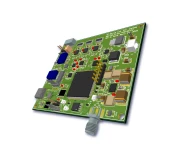
Description
Dual Port Modulator Bias Controller – MBC-DUAL-BIAS-SIL
The MBC-DUAL-BIAS-SIL Dual Port Modulator Bias Controller is a high‑performance, OEM‑grade solution engineered specifically for demanding analog and photonic systems that require extremely stable null locking of Mach–Zehnder (MZ) and silicon photonic modulators. Designed for use with dual DC‑port modulators, this controller enables very high extinction ratios at the null operating point, helping system designers achieve superior signal fidelity, reduced noise, and improved dynamic range in applications such as analog optical links, test and measurement setups, coherent communication systems, and advanced photonic integration platforms.
In contrast to simple biasing circuits or manual tuning methods often used in basic MZ modulator setups, this controller provides a dedicated null‑locking architecture that continuously maintains the modulator at its minimum transmission point. By operating exclusively in null locking mode, it is optimized for applications where deep suppression of the optical carrier or unwanted amplitude components is critical. The typical extinction ratio achievable in null mode is specified up to 52 dB (subject to the intrinsic modulator characteristics), which places this unit among the higher‑performance bias control solutions available for dual‑port MZ modulators in the 1000–1650 nm wavelength band.
The MBC-DUAL-BIAS-SIL supports an internal and external photodetector configuration, giving users flexibility in how they tap and monitor optical power in their systems. An integrated photodiode handles most common use cases, while an external photodetector input allows optimization of detection sensitivity, wavelength response, or power handling when used with different modulators or optical setups. The detector input is designed for operation over a wide input range, with sensitivity down to approximately –55 dBm and typical operation around –40 dBm at the minimum attenuation point, ensuring stable feedback even in low‑power environments or with small tap ratios.
Electrically, the controller provides a generous bias voltage range from –14 V to +14 V and supports user‑configurable bias currents up to 250 mA per port. This allows it to accommodate a wide variety of LiNbO₃ and silicon modulators, including those with higher drive requirements or non‑standard operating points. Multiple modulators can be managed by a single controller, enabling more compact and cost‑effective system architectures where several channels must be biased and stabilized simultaneously. This capability is particularly useful in multi‑channel analog systems, WDM platforms, and photonic integrated circuits that host several modulators on the same board.
A built‑in pilot tone system is used to implement the null locking feedback loop. The pilot tone amplitude is adjustable via the graphical user interface (GUI), with a modulation depth at null on the order of 0.1% and pilot tone levels adjustable up to 250 mV peak‑to‑peak. This ensures that the feedback signal is strong enough for robust locking while keeping additional modulation of the optical signal extremely small, which is important in high‑performance analog and RF‑over‑fiber links where added distortion or noise must be minimized. For specialized setups or during testing, the user can disable the pilot tone and operate the device in manual mode, offering further flexibility in optimizing overall system performance.
To support fast installation and straightforward integration, the controller provides several distinct operating modes. In calibration mode, the device automatically determines the proper null point for the connected modulators and optimizes internal settings. Once calibrated, locking mode maintains the operating point with high stability over temperature variations and slow drifts. A dedicated calibration‑off mode is available for rapid system setup directly into locking, minimizing downtime and simplifying complex multichannel configurations. Additionally, a pulse mode is included for more precise null locking with pulsed optical signals, such as those encountered in time‑domain measurement systems, pulsed laser setups, or high‑speed digital and RF pulse applications where classical continuous‑wave lock algorithms may not suffice.
OZ Optics MBC Dual Bias SIL Modulator Bias Controller High Extinction Ratio
Specifications
| Product Type: | MBC |
|---|---|
| Modulation Type: | Other |
| Detector Input Power: | -55 dBm |
| Locking Slope: | Positive, Negative |
| Locking Mode: | Quad+, Quad-, Null, Peak Positions |
| Photodetector Type: | External |
| Tunability: | Tunable |
| Optical Wavelength Range: | 1000–1650 nm |
| Detector Input Power (min): | -55 dBm |
| Detector Input Power (max): | -40 dBm |
| Null Mode Extinction Ratio (min): | 52 dB |
| DC Negative Power Voltage (min): | -17 V |
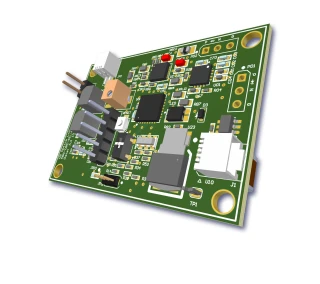
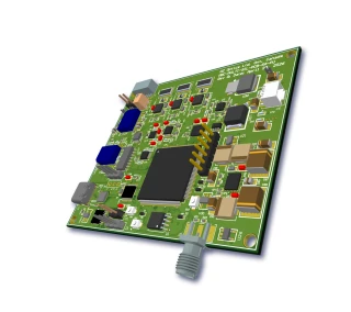
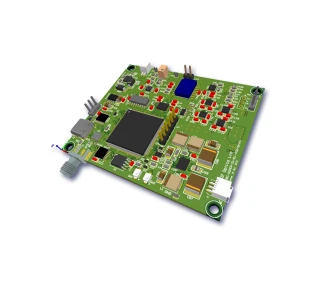
| PCB Board Size: | 2.7 x 3.27 x 0.65 inch |
| Number Of Controlled Modulators: | 3 |
| Bias Port Max Current: | 250 mA |
| Bias Port Voltage Adjustment Range: | -12 to +12 V |
| Weight: | 0.2 lb |
| Dimensions: | 2.7 x 3.57 x 0.65 inch |
| Storage Temperature Range: | -40 to 85 °C |
| Operating Temperature Range: | 0 to 70 °C |
| DC Negative Power Current (typ): | 105 mA |
| DC Positive Power Current (typ): | 190 mA |
| DC Negative Power Voltage (max): | -16 V |
| DC Negative Power Voltage (typ): | -16.5 V |
| DC Positive Power Voltage (max): | 17 V |
| DC Positive Power Voltage (typ): | 16.5 V |
| DC Positive Power Voltage (min): | 16 V |
| Pilot Tone Amplitude (max): | 250 mV Vpp |
| Pilot Tone Amplitude (typ): | 2 mV Vpp |
| Pilot Tone Amplitude (min): | 0 mV Vpp |
| Pilot Tone Modulation Depth (NULL): | 0.1 % |
| Bias Current (max, Configurable): | 250 mA |
| Bias Voltage Range: | -14 to +14 V |
Got questions about specs? Use the inquiry form to ask.
 Download Data Sheet

Features
- High-Performance Dual-Port Modulator Bias Control
Specifically engineered for dual DC-port LiNbO3 Mach-Zehnder (MZ) modulators and silicon photonic modulators, enabling extremely high extinction ratio operation in demanding analog and coherent optical systems. - Null-Locking Only Architecture for Maximum Extinction Ratio
Optimized for null bias locking to reach very high extinction ratios (up to 52 dB typical, depending on the modulator), ideal for applications requiring ultra-deep modulation suppression and low residual carrier. - Dual-Bias-SIL Design with Control of Three Modulators
One compact controller can independently control up to three modulators, significantly reducing system cost and footprint in multi-channel or multi-wavelength optical links. - Flexible Bias Voltage and High Current Drive
Wide bias range from -14 V to +14 V and bias current up to 250 mA per port (user-configurable limit), supporting a broad spectrum of LiNbO3, silicon, and custom modulators with varying drive requirements. - Two Operating Modes for Fast Setup and Stable Operation
Integrated Calibration Mode for initial modulator characterization and Locking Mode for long-term stable bias control, simplifying deployment in production and laboratory environments. - Calibration Off Mode for Rapid System Bring-Up
A dedicated Calibration Off option allows the system to start quickly directly in locking mode, minimizing setup time in manufacturing and field deployments. - Pulse Mode for Advanced Pulsed Applications
Specialized Pulse Mode enables more precise null locking under pulsed optical or electrical drive conditions, improving extinction and stability in high-speed pulsed, QKD, and time-domain applications. - Integrated and External Photodiode Support
Includes one integrated photodiode (PD) and an input for an external photodetector, providing flexibility for different optical layouts, tap ratios, and wavelength ranges (standard operation over 1000–1650 nm, extendable with alternative PDs). - Wide Optical Input Power Range
Supports detector input levels from approximately -55 dBm to -40 dBm (at minimum attenuation), allowing operation with low tap power and minimizing intrusion on the main signal path. - Fine Pilot Tone Control for Robust Locking
Utilizes a low-depth pilot tone with modulation depth as low as 0.1% in null mode and adjustable pilot tone amplitude from 0 to 250 mVpp, ensuring accurate bias control while minimally impacting signal integrity. - GUI-Controlled Operation via USB Type‑C
Comes with a USB Type‑C interface and an intuitive graphical user interface (GUI) to configure all operating parameters, monitor status, adjust pilot tone amplitude, and optionally disable the pilot tone in manual mode. - Full Remote Monitoring and Control
All operating settings are remotely controllable and all parameters can be read and displayed in the GUI, simplifying integration into automated test setups, OEM systems, and remote-managed platforms. - Optional RS232 Interfaces for System Integration
Available with RS232 DB9 or RS232 Flywires (RS232FW) as an option, facilitating integration into existing control infrastructures and embedded controllers in telecom, datacom, and sensing systems. - Compact OEM-Friendly PCB Form Factor
Miniature PCB design of approximately 2.7" × 3.57" × 0.65" and weight around 0.2 lb makes it ideal for OEM modules, rack systems, and space-constrained photonic integrated solutions. - Wide Operating Temperature Range
Designed for reliable operation from 0°C to +70°C with storage capability from -40°C to +85°C, suitable for lab, industrial, and controlled-environment field applications. - Stable Dual-Supply Power Architecture
Operates from symmetric supply rails of about +16 to +17 V and -16 to -17 V, with modest current consumption (approximately 190 mA positive and 105 mA negative), simplifying power design in complex optical subsystems.
Applications
- Bias Control for Lithium Niobate (LN) Mach-Zehnder Modulators – Provides precise dual-port DC bias control for LiNbO3 MZ modulators used in analog and digital fiber optic links, enabling stable operation at the null point for maximum extinction ratio and low signal distortion.
- Silicon Photonics Modulator Driver Electronics – Optimized for silicon-based MZ and IQ modulators with two DC ports, ensuring long-term bias stability in integrated photonic circuits for data center interconnects, short-reach links, and on-chip optical signal processing.
- High Extinction Ratio Analog Fiber Optic Links – Maintains the modulator at the precise null operating point to achieve very high extinction ratios (up to ~52 dB, limited by the modulator), ideal for low-noise analog RF-over-fiber and microwave photonics links.
- RF over Fiber and Microwave Photonics Systems – Used in RF-over-fiber modulators to minimize intermodulation distortion and enhance spurious-free dynamic range (SFDR) by keeping the operating point accurately locked at null.
- Coherent Optical Communication Testbeds – Supports bias control of in-phase and quadrature arms of dual-drive or dual-port modulators in coherent transmitters, ensuring stable amplitude and phase for high-order modulation formats during R&D and system prototyping.
- Optical Signal Suppression and Carrier Nulling – Enables deep carrier suppression for applications requiring high extinction of the optical carrier or sidebands, such as optical single-sideband (OSSB) generation and advanced modulation schemes.
- Photonic R&D and Laboratory Experiments – Compact OEM board ideal for labs and universities working with MZ modulators, providing a turnkey solution for null-point locking, calibration, and bias optimization in experimental setups.
- Production Test and Automated Modulator Characterization – Integrated USB and optional RS232 interfaces allow remote control and scripting for automated bias calibration, stability testing, and characterization of LN and silicon modulators in manufacturing environments.
- Fiber Optic Sensing and Interferometric Systems – Used to stabilize Mach-Zehnder interferometers employed in optical sensors and phase-sensitive measurement systems by maintaining consistent operating conditions at or near the null point.
- Pulsed Laser and Pulse-Shaping Applications – Pulse mode operation allows accurate null locking in pulsed systems, such as optical pulse carving, pulse picking, and temporal modulation where precise extinction of pulses or background is required.
- Optical Arbitrary Waveform Generation (O-AWG) – Ensures stable biasing of modulators used for shaping complex optical waveforms, helping to maintain waveform fidelity and repeatability in advanced waveform generation platforms.
- Quantum Communication and Quantum Optics Experiments – Provides stable amplitude control for modulators used in quantum key distribution (QKD), entanglement experiments, and single-photon modulation where high extinction and low drift are critical.
- Optical Metrology and Precision Measurement – Enhances stability in optical metrology systems that rely on high-extinction modulation for accurate amplitude referencing, dynamic range extension, and calibration routines.
- Signal Gating and Optical Shuttering – Used to implement high-extinction on/off optical gating for systems requiring precise light suppression, such as test setups, optical switching, and protection circuits.
- WDM and Subcarrier Multiplexing Experiments – Stabilizes modulators used to encode multiple RF subcarriers or WDM channels on a single optical carrier, minimizing crosstalk and amplitude drift.
- Field-Deployable and OEM Integrated Systems – Small PCB form factor (approx. 2.7" x 3.57" x 0.65") allows easy integration inside optical instruments, transceiver modules, and custom OEM photonic systems that require embedded modulator bias control.
- Multi-Modulator Control Platforms – Capable of controlling up to three modulators from a single controller board, well suited for systems that incorporate multiple MZ modulators, IQ modulators, or cascaded modulation stages.
- Remote and Computer-Controlled Photonic Systems – USB Type-C interface with GUI and optional RS232 connectivity enables remote monitoring and control of bias voltages, pilot tones, and operating modes in rack-mounted or unattended systems.
Frequently Asked Questions
What is the MBC-DUAL-BIAS-SIL Modulator Bias Controller and what does it do?
Which modulators and wavelengths are compatible with the MBC-DUAL-BIAS-SIL?
How does the null-locking operation and pilot tone of the MBC-DUAL-BIAS-SIL work?
What are the key electrical and optical specifications of the MBC-DUAL-BIAS-SIL?
How do I connect this bias controller to my modulator and photodiode in a system?
What interfaces and control options does the MBC-DUAL-BIAS-SIL provide (GUI, USB, RS232)?
What part numbers, connector options, and customization possibilities are available?
Got more questions? Use the inquiry form to ask the supplier directly.
Similar Products


Your inquiry has been received.
Create an account by adding a password
Why create an account?
- Auto-complete inquiry forms
- View and manage all your past messages
- Save products to your favorites
- Close your account anytime — no hassle