
Description
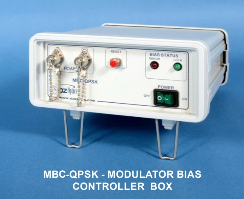
The MBC-QPSK Modulator Bias Controller Box is a compact bench‑top solution engineered to stabilize and optimize dual‑polarization (DP) and single‑polarization (SP) QPSK and DQPSK optical modulators used in 80 Gbit/s and advanced coherent transmission systems. Designed for laboratory, R&D, and production environments, this controller maintains critical bias points of complex nested Mach‑Zehnder modulator structures, helping researchers and system designers achieve consistent phase modulation, excellent extinction ratios, and long‑term stability without constant manual retuning.
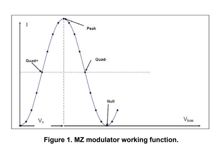
Modern coherent transmission formats such as DQPSK, QPSK, and higher‑order QAM demand precise control of multiple internal phase and intensity modulators. A typical DP or SP QPSK modulator combines several phase modulators with multiple Mach‑Zehnder interferometers, resulting in three bias points per QPSK channel (and six total for dual‑polarization configurations) that must be actively maintained. The MBC‑QPSK controller automates this task by simultaneously locking the first and second child modulators at their Null (or Peak) operating points and the parent modulator at the Quad operating point, ensuring highly repeatable operating conditions for advanced modulation experiments and system integration.
Tailored for demanding optical communication testbeds, the controller supports operation at both 1300 nm and 1550 nm, making it suitable for metro, long‑haul, and ultra‑long‑haul transmission research. An integrated photodiode allows direct monitoring of the optical output of the modulator, while internal pilot tone techniques are used to track and stabilize the bias points. With a typical detector input power range of about −25 dBm to −10 dBm, the controller can reliably sense small fractions of the transmitted signal via low‑ratio tap couplers, as commonly used in coherent system laboratories.
A key strength of this controller is its flexible bias control capability. It offers a wide differential bias voltage range from approximately −25 V to +25 V, and a single‑ended range of about −12.5 V to +12.5 V, accommodating a broad spectrum of LiNbO₃ and similar electro‑optic modulators on the market. In Null mode, the system is designed to achieve high extinction ratios, typically on the order of 25 dB to 40 dB, which is essential for generating clean, high‑contrast optical waveforms and for minimizing unwanted residual intensity modulation that can degrade system performance.
The MBC‑QPSK controller employs low‑depth pilot tones, typically around 0.1% modulation depth in both Quad and Null modes, at a pilot tone frequency on the order of a few kilohertz (around 4 kHz). These tones are carefully chosen to enable precise bias tracking while exerting minimal influence on the data‑bearing optical signal. In automated mode, the controller continuously adjusts the bias voltages to compensate for thermal drifts, aging, and environmental variations, preserving the optimal operating point over long measurement runs or extended system uptime.
For advanced modulation research, the controller supports three main operation profiles: DQPSK, QAM, and an Arbitrary‑waveform mode. In DQPSK and QPSK modes, it is optimized for typical nested Mach‑Zehnder configurations used in 80 Gbit/s and beyond, ensuring that both in‑phase and quadrature arms in single or dual polarization remain correctly biased. In QAM and arbitrary‑waveform modes, it provides the flexibility needed for complex amplitude‑ and phase‑shaped constellations, waveform synthesis experiments, or custom modulator configurations that depart from standard telecom implementations.
A user‑friendly USB computer interface gives complete remote control over all bias channels. Through a graphical user interface, users can select the working slope (positive or negative) at Null or Peak, configure which modulators use pilot tone locking, and read back both photodiode input power and applied bias voltages in real time. Automation and manual modes are both supported: in automated operation the pilot tone‑based control loops maintain optimum bias, while in manual mode users can disable pilot tones for any subset of modulators and perform fine bias adjustments directly from the computer. This dual approach is especially valuable during initial system bring‑up, experimental configuration changes, and troubleshooting.
The integrated design also simplifies optical and electrical setup. With one photodiode already built into the controller, users can route a small fraction of the modulator output to the unit without needing separate detection hardware, thus minimizing external components and cabling. The compact housing (approximately 15.5 cm x 20.3 cm x 6.9 cm) and low weight (around 0.95 kg) make the unit well suited for dense lab benches, mobile test setups, and multi
QPSK-DP-SP Modulator Bias Controller Box
Specifications
| Product Type: | QPSK-DP/SP |
|---|---|
| Modulation Type: | QPSK, DQPSK |
| Detector Input Power: | -25 dBm |
| Locking Slope: | Positive, Negative |
| Locking Mode: | Quad+, Quad-, Null, Peak Positions |
| Photodetector Type: | Integrated |
| Tunability: | Tunable |
| Detector Input Power (Min, Max): | -25 dBm to 25 dBm |
| Detector Input Power (Typ): | -10 dBm |
| Optical Wavelength: | 1300/1550 nm |
| Bias Voltage (Differential, Min): | -25 V |
| Bias Voltage (Differential, Max): | 25 V |
| Bias Voltage (Single End, Min): | -12.5 V |
| Bias Voltage (Single End, Max): | 12.5 V |
| Null Mode Extinction Ratio (Max): | 40 dB |
| Locking Slope: | Positive or Negative |
| Locking Mode (Child Modulators): | Null (Peak) positions |
| Locking Mode (Parent Modulator): | Quad+ or Quad- position |
| Pilot Tone Modulation Depth (QUAD): | 0.1% |
| Pilot Tone Modulation Depth (NULL): | 0.1% |
| Pilot Tone Frequency: | 4000 Hz |
| Power Voltage (Min): | 90 V AC |
| Power Voltage (Typ): | 110 V AC |
| Power Voltage (Max): | 240 V AC |
| Power Current: | 0.65 A AC |
| Operating Temperature (Min): | 0 °C |
| Operating Temperature (Max): | 70 °C |
| Storage Temperature (Min): | -40 °C |
| Storage Temperature (Max): | 85 °C |
| Dimension: | 15.5 cm × 20.3 cm × 6.9 cm (6.1 in × 8 in × 2.7 in) |
| Weight: | 0.95 kg (2.1 lb) |
| Number Of Controlled Modulators: | Six |
Got questions about specs? Use the inquiry form to ask.
 Download Data Sheet

Features
- Dedicated DP/SP QPSK & DQPSK Modulator Control – Designed specifically for dual‑polarization and single‑polarization QPSK modulators used in 80 Gbit QPSK and QAM coherent transmission systems, ensuring optimal phase and amplitude stability.
- Simultaneous Control of Up to Six Modulators – One controller manages six modulators (two “child” phase modulators and one “parent” Mach‑Zehnder per QPSK arm), minimizing system complexity and rack space in multi‑channel links.
- Automatic Null/Peak & Quadrature Biasing – Automatically locks the 1st and 2nd modulators at Null/Peak positions and the 3rd modulator at the Quad (quadrature) point, maintaining optimum operating bias for high‑quality constellation generation.
- User‑Selectable Locking Slope – Positive or negative locking slopes can be selected through the GUI, allowing compatibility with a wide range of lithium‑niobate and InP external modulators and different RF/optical configurations.
- Three Optimized Operation Modes – Supports DQPSK, QAM, and Arbitrary‑waveform modes so the same controller can be used from simple DQPSK through advanced higher‑order modulation and custom waveform experiments.
- Integrated High‑Sensitivity Photodiode – Built‑in photodiode (PD) with –25 dBm to –10 dBm detector input power range eliminates the need for external detectors and simplifies bias monitoring and locking feedback loops.
- High Extinction Ratio in Null Mode – Typical 25–40 dB extinction ratio in Null mode enables deep modulation, improved OSNR performance, and cleaner eye diagrams in coherent and direct‑detection systems.
- Wide Bias Voltage Range – Supports ±25 V differential and ±12.5 V single‑ended drive, covering most commercial LiNbO3 QPSK/DQPSK modulators and allowing flexible integration into existing optical benches.
- Low Pilot‑Tone Modulation Depth – Pilot tones with as little as 0.1% modulation depth in both Null and Quad modes preserve signal integrity and minimize impact on transmitted data, while still ensuring robust bias locking.
- Stable Pilot‑Tone Frequency – Uses a pilot tone at approximately 4 kHz, a well‑proven frequency region for bias control that helps avoid interference with typical data channels and low‑frequency system noise.
- Full USB Remote Control – All parameters can be set and monitored via a USB computer interface, enabling easy integration into automated test setups, remote labs, and manufacturing environments.
- Automatic or Manual Bias Modes – Choose between fully automatic closed‑loop control and manual tuning; pilot tone can be disabled per modulator to support manual bias optimization, characterization, or custom locking schemes.
- Real‑Time Monitoring via GUI – User‑friendly graphical interface provides read‑back of input power to the PDs and actual bias voltages, improving visibility, diagnostics, and repeatability in complex optical experiments.
- Bench‑Top, Full‑Function MBC Platform – Desktop “box” implementation of OZ Optics’ MBC family consolidates control electronics, PDs, and user interface in one unit for rapid lab deployment and straightforward system upgrades.
- Compact, Lightweight Design – Small footprint (approx. 15.5 cm × 20.3 cm × 6.9 cm) and low weight (~0.95 kg) save valuable optical table and rack space, making it ideal for crowded research labs and production lines.
- Wide Operating Temperature Range – Reliable operation from 0 °C to 70 °C with storage from –40 °C to +85 °C ensures stable performance in standard laboratories, telecom environments, and controlled manufacturing floors.
- Universal AC Power Compatibility – Accepts 90–240 VAC input at about 0.65 A, compatible with global mains standards for easy deployment worldwide without additional power conversion hardware.
- Enhanced Link Reach and Spectral Efficiency – Optimized DQPSK/QPSK bias control improves dispersion tolerance, extends total link reach, and supports tighter channel spacing in DWDM systems, resulting in higher spectral efficiency.
- Ideal for Coherent Research & System Prototyping – Well‑suited for coherent receiver/transmitter experiments, advanced modulation format development, high‑capacity backbone prototyping, and academic research in
Applications
- High‑capacity coherent optical transmission systems
Enables precise bias control for DP/SP QPSK and DQPSK modulators in 40G, 80G and higher‑rate coherent links, improving constellation stability and reach in long‑haul and metro DWDM networks. - QPSK and QAM modulation format research
Ideal for laboratory development of advanced modulation schemes (QPSK, DQPSK, 8‑QAM, 16‑QAM) where stable bias points on nested Mach‑Zehnder structures are required for repeatable experiments. - Coherent receiver and transceiver prototyping
Used in building and evaluating coherent optical transceivers, providing stable phase and amplitude control for I/Q modulators in dual‑polarization transmitter testbeds. - Performance characterization of integrated optical modulators
Supports evaluation of DP‑QPSK, DQPSK and IQ modulators on LiNbO3 or silicon photonics platforms by ensuring well‑defined null, peak, and quadrature bias during insertion loss, Vπ, and extinction ratio measurements. - WDM system experiments and channel loading
Facilitates generation of stable, phase‑encoded carriers for multi‑channel DWDM test setups, system margin studies, and nonlinear fiber propagation experiments. - Fiber‑optic communication teaching and training labs
Provides a user‑friendly bench‑top platform for universities and training centers to demonstrate coherent modulation, bias locking concepts, pilot‑tone based control, and eye‑diagram/constellation evolution. - Optical transmission impairment studies
Ensures modulation stability for experiments investigating chromatic dispersion, polarization mode dispersion, nonlinear effects, OSNR limits, and FEC performance in coherent systems. - Automation of modulator bias control in test setups
Replaces manual bias tuning with USB‑controlled automatic locking, enabling long‑term unattended measurements in R&D and characterization benches for high‑speed optical components. - Arbitrary waveform and advanced signal generation
Works with arbitrary waveform generators and DSP‑based pattern generators in “Arbitrary‑waveform” mode to support custom phase and amplitude modulation formats for advanced research. - High‑spectral‑efficiency transmission demonstrations
Supports QPSK/QAM demonstrations focused on spectral efficiency optimization, superchannel generation, and flexible‑grid or elastic optical network research. - System integration in prototype optical networks
Can be embedded in experimental network nodes or transmitter racks to stabilize complex modulator biasing in field or lab trials of new coherent technologies. - Optical signal quality and BER testing
Provides stable quadrature and null operating points to minimize drift‑induced penalties when measuring BER, EVM, and Q‑factor of coherent links or components. - Polarization‑multiplexed signal generation
Controls the multiple child and parent modulators in dual‑polarization QPSK structures, enabling reliable generation of polarization‑multiplexed signals for PM‑QPSK experiments. - Long‑duration stability and drift studies
Maintains optimal modulator bias over temperature and time, making it suitable for aging tests, thermal drift studies, and reliability qualification of optical modulators. - Optical network equipment vendor R&D
Used by system and module manufacturers to accelerate design cycles of coherent transmitters, line cards, and pluggable coherent optics that rely on nested Mach‑Zehnder modulators. - Test and measurement equipment integration
Complements optical spectrum analyzers, coherent receivers, and high‑speed oscilloscopes by providing a stable modulated optical source for calibration and verification workflows. - Quantum and advanced photonics experimentation
Applicable in phase‑sensitive or multi‑path interferometric experiments where precise and stable phase control through Mach‑Zehnder modulators is required. - OEM and custom photonic system development
Serves as a ready‑to‑use bias control platform for OEMs integrating DP/SP QPSK or DQPSK modulators into custom optical instruments, prototypes, and specialty communication systems. - Educational demonstrations of biasing techniques
Demonstrates null, peak, and quadrature biasing, pilot‑tone based feedback control, and slope selection (positive/negative) for students and engineers learning about modulator physics. - General coherent optical lab infrastructure
Acts as a versatile, compact building block for any photonics laboratory requiring repea
Frequently Asked Questions
What is the OZ Optics MBC-QPSK Modulator Bias Controller Box and what applications is it designed for?
Which modulators and bias points can the MBC-QPSK control simultaneously?
What operating modes does the MBC-QPSK support (DQPSK, QAM, Arbitrary) and when should each be used?
How does the bias locking work, and what are Null/Peak and Quad points in this controller?
What are the key electrical and optical specifications, including input power, wavelength range, and bias voltage?
How is the MBC-QPSK controlled and monitored (GUI, USB, automation vs. manual bias control)?
What are the physical characteristics of the MBC-QPSK and how does it compare to other bias controllers in size and integration?
Got more questions? Use the inquiry form to ask the supplier directly.
Similar Products
Your inquiry has been received.
Create an account by adding a password
Why create an account?
- Auto-complete inquiry forms
- View and manage all your past messages
- Save products to your favorites
- Close your account anytime — no hassle