


Description
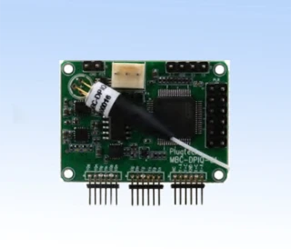
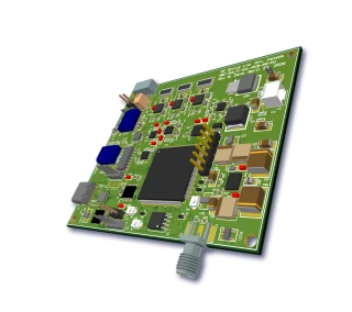
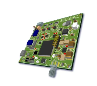
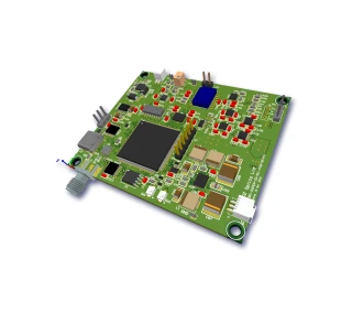
The MBC-D Ditherless Modulator Bias Controller is a compact, OEM-ready solution designed to provide precise, long-term stable bias control for optical modulators and tunable filters. Engineered for integration into demanding photonics systems, this controller maintains the operating point of a Mach-Zehnder (MZ) intensity modulator or Fabry-Perot tunable filter without introducing any dither or pilot tone. By avoiding additional modulation on the optical or electrical signal, it preserves the integrity of high-performance analog and digital links, making it ideal for RF-over-fiber, coherent communication testbeds, sensing, and instrumentation applications.
Unlike traditional bias controllers that rely on dithering techniques, the ditherless approach used in this unit eliminates unwanted spurious tones and signal degradation. This is particularly important in analog and microwave photonics links where even low-level pilot tones can compromise spurious-free dynamic range (SFDR) and overall system linearity. The MBC-D continuously locks the modulator or filter to the desired reference point along its periodic transfer function, compensating for temperature drift, aging, and environmental fluctuations. When necessary, the locking slope can be reversed via a simple on-board switch, allowing the controller to stabilize different operating points such as quadrature, minimum, or maximum transmission depending on the application.
Internally, the controller incorporates two integrated photodiodes to monitor optical power and generate the feedback signals required for robust control. It accepts very low input optical powers down to approximately –50 dBm and input photocurrents in the microampere range, yet still achieves high locking accuracy on the order of 0.1%. This wide dynamic range simplifies system design, enabling reliable performance over a broad range of optical power levels and link conditions. For more specialized control schemes, an external reference voltage can be specified at the time of order, allowing the bias controller to track a user-defined operating level instead of relying solely on its internal reference.
The MBC-D supports a DC bias output range of –10 V to +10 V, making it compatible with a wide variety of LiNbO₃ Mach-Zehnder modulators and other electro-optic devices with similar bias characteristics. Typical supply voltages are ±12 V (with a usable range of approximately ±10 V to ±15 V), and the unit draws modest supply currents, facilitating integration into space-constrained OEM modules, benchtop instruments, or field-deployed systems. When the monitored operating point drifts outside the specified locking window, the controller automatically pulls the bias back toward the desired working point near 0 V, enhancing resilience against sudden perturbations and ensuring continuous, uninterrupted operation.
Designed with practicality in mind, the controller’s footprint of roughly 2.35 x 1.35 x 0.5 inches allows straightforward mounting on printed circuit boards or within compact optical subassemblies. Its operating temperature range from 0 to 70 °C supports use in typical laboratory and controlled-environment deployments, while storage down to –40 °C and up to 80 °C ensures survivability during transport and non-operational periods. An onboard LED alarm provides a clear visual indication in overtuning or fault conditions, assisting engineers and technicians in rapid diagnostics during system bring-up and maintenance.
In modern optical systems where stability, dynamic performance, and signal purity are critical, the MBC-D Ditherless Bias Controller offers an advanced alternative to conventional dither-based bias control schemes. Its combination of high accuracy, fast response, and broad compatibility with Mach-Zehnder modulators and Fabry-Perot tunable filters makes it an attractive building block for next-generation communication, test and measurement, and photonic sensing platforms that cannot tolerate pilot tones or additional noise in the signal path.
Ditherless Modulator Bias Controller
Specifications
| Product Type: | MBC |
|---|---|
| Modulation Type: | Other |
| Detector Input Power: | -50 dBm |
| Locking Slope: | Positive, Negative |
| Locking Mode: | Quad+, Quad-, Null, Peak Positions |
| Photodetector Type: | Unspecified |
| Tunability: | Tunable |
| Input Signal Current: | 0.1×10^-5 to 1 mA |
| Input Optical Power Range: | -50 to 0 dBm |
| Locking Accuracy: | 0.1 % |
| DC Bias Voltage Range: | -10 to +10 V |
| Positive Power Supply Voltage: | 10 to +15 V (typ. 12 V) |
| Negative Power Supply Voltage: | -10 to -15 V (typ. -12 V) |
| Positive Supply Current: | 35 mA |
| Negative Supply Current: | 20 mA |
| Operating Temperature: | 0 to 70 °C |
| Storage Temperature: | -40 to 80 °C |
| Dimensions (L × W × H): | 2.35 × 1.35 × 0.5 inch |
Got questions about specs? Use the inquiry form to ask.
 Download Data Sheet

Features
- True ditherless operation – no pilot tone required
Maintains precise bias control without superimposing a pilot tone on the signal, eliminating added modulation noise and signal distortion, which is critical for high‑performance analog and coherent optical systems. - High‑accuracy bias locking for Mach–Zehnder (MZ) modulators
Precisely locks the operating point of MZ modulators to quadrature, maximum, or minimum transmission, improving extinction ratio, linearity, and long‑term stability in intensity and phase modulation applications. - Compatible with Fabry–Perot tunable filters and fiber loop‑back control
Provides stable feedback control for Fabry–Perot filters and fiber‑based cavities, ensuring accurate wavelength selection and minimizing drift in tunable and sensing systems. - Wide dynamic range optical and electrical input
Operates reliably from very low optical powers (down to –50 dBm) and ultra‑low photodiode currents (as low as 0.1×10⁻⁵ mA), making it suitable for both low‑power laboratory setups and higher‑power telecom links. - High locking accuracy (≈0.1%)
Tight control of the bias point minimizes residual amplitude modulation and improves signal‑to‑noise ratio, enabling demanding analog optical links, RF‑over‑fiber, CATV, and coherent communication systems. - Broad DC bias voltage range (–10 V to +10 V)
Supports a ±10 V DC bias output range for direct driving of a wide variety of LiNbO₃ MZ modulators and other electro‑optic or tunable optical components without additional bias electronics. - Fast response for dynamic operating conditions
Rapid feedback loop response compensates drift due to temperature changes, device aging, and environmental variations, maintaining stable operation even in rapidly changing system conditions. - Selectable locking slope for periodic transfer functions
On‑board sliding switch allows the user to choose the locking slope (positive or negative) to match periodic device transfer curves, enabling locking to the desired operating point across multiple applications. - Integrated dual photodiode inputs
Two built‑in photodiodes simplify system integration and allow power monitoring from different points in the optical path (e.g., MZ modulator outputs or Fabry–Perot reflections) without additional detector modules. - Support for external reference voltage
Accepts an external reference voltage (when specified at order) so users can define custom operating points or implement advanced control schemes synchronized with other system electronics. - Compact OEM‑friendly footprint
Small form factor (approx. 2.35 × 1.35 × 0.5 in.) is ideal for integration into OEM modules, benchtop instruments, and field‑deployed systems where space and weight are constrained. - Wide operating temperature range (0–70 °C)
Designed for reliable performance over standard laboratory and many field environments, reducing the need for additional thermal control in telecom and industrial systems. - Standard dual‑supply operation
Operates from common ±10 to ±15 V supplies (typ. ±12 V), with low power consumption (≈35 mA positive, 20 mA negative), simplifying power‑rail design in complex photonic subsystems. - Overtuning alarm with LED indication
Front‑panel LED alerts the user when the bias voltage approaches or exceeds safe tuning limits, aiding in troubleshooting, system protection, and safe device characterization. - Non‑intrusive performance for analog and coherent links
Because no dither tone is added, the controller does not degrade signal purity, error‑vector magnitude, or phase noise, making it suitable for high‑order modulation formats and low‑noise RF photonic links. - Ideal for RF‑over‑fiber, CATV, lidar, and sensing applications
Enhances long‑term stability and linearity in demanding use cases such as RF photonic distribution, cable TV transmission, FMCW lidar, interferometric sensors, and quantum optics experiments. - Easy integration into polarization‑maintaining (PM) and SM systems
Designed to work seamlessly with PM fiber MZ modulators and standard single‑mode configurations commonly used in telecom, test & measurement, and research laboratories.
Applications
- Bias control for LiNbO3 Mach–Zehnder (MZ) intensity modulators in analog and digital fiber‑optic links, ensuring operation at quadrature or null without adding pilot tones.
- High‑linearity analog optical transmission systems (CATV, RF‑over‑fiber, microwave photonics) where any dither or pilot tone would degrade SFDR and overall signal quality.
- Coherent optical communication testbeds, providing stable biasing of MZ modulators used for QPSK, QAM, and advanced modulation format generation without disturbing phase or amplitude.
- Fabry–Perot tunable filter bias and wavelength locking, maintaining the filter at a desired resonance point for dense WDM channel selection and optical spectrum shaping.
- Optical sensor and interferometric systems (fiber interferometers, gyroscopes, and strain/temperature sensors) requiring stable bias control of interferometric elements for accurate phase and amplitude measurement.
- Photonic RF and microwave signal processing, stabilizing modulators used in optical upconversion, frequency mixing, and phased‑array beamforming networks.
- Electro‑optic research and laboratory experiments where precise and repeatable bias control of periodic transfer‑function devices (MZ, EO modulators, etalons) is necessary over long measurement cycles.
- Optical arbitrary waveform generation and pulse shaping, keeping modulators and filters at optimal working points for high‑fidelity waveform synthesis.
- Quantum optics and quantum communication setups using MZ interferometers or cavity filters, where extra tones cannot be tolerated due to low‑signal levels and noise sensitivity.
- Integrated photonic circuit evaluation, providing an external, high‑accuracy bias controller for on‑chip MZ modulators and resonant structures during characterization and production test.
- OEM embedded bias control in optical modules (transmitters, modulator drivers, tunable filter modules) requiring compact, board‑mountable bias electronics with on‑board photodiodes.
- Long‑term bias drift compensation in field‑deployed systems, automatically pulling the bias back to the desired operating point under temperature changes and component aging.
- Feedback‑controlled optical power stabilization using the built‑in photodiodes and external reference voltage to hold a constant output power or extinction ratio.
- Test and measurement equipment, such as optical modulators in bit‑error‑rate testers, arbitrary waveform generators, and optical communication analyzers that must remain locked for extended periods.
- R&D on novel electro‑optic materials and devices, providing a flexible, tunable, ditherless bias platform to characterize periodic transfer functions without adding measurement artifacts.
Frequently Asked Questions
What is the OZ Optics ditherless modulator bias controller and what does it do?
How does a ditherless bias controller work compared to conventional dither-based bias control?
What are the main applications of the OZ Optics ditherless modulator bias controller?
What are the key electrical and optical specifications of the MBC-D bias controller?
How do I connect the ditherless bias controller to a Mach–Zehnder modulator or Fabry–Perot filter?
What are the advantages of using a ditherless bias controller in analog and RF-over-fiber systems?
How do I order and customize the OZ Optics MBC-D bias controller for my application?
Got more questions? Use the inquiry form to ask the supplier directly.
Similar Products


Your inquiry has been received.
Create an account by adding a password
Why create an account?
- Auto-complete inquiry forms
- View and manage all your past messages
- Save products to your favorites
- Close your account anytime — no hassle