


Description
Super Modulator Bias Controller for High‑Performance Mach–Zehnder Modulation
The MBC‑SUPER Modulator Bias Controller is a compact, full‑function OEM solution designed to deliver highly stable, long‑term bias control for LiNbO3 and other Mach–Zehnder (MZ) optical modulators. In advanced fiber‑optic communication, sensing, and test setups, even slight DC drift or temperature variation can push an MZ modulator away from its optimal operating point, degrading extinction ratio, distorting waveforms, and increasing bit‑error rates. The MBC‑SUPER continuously tracks and corrects the operating point of the modulator at Quad+, Quad‑, Null, or Peak, ensuring consistent modulation depth and superior signal fidelity in both CW and pulse‑mode systems.
With its integrated pilot‑tone based digital control loop and selectable locking modes, the controller is engineered to meet the requirements of modern coherent transmission, analog RF‑over‑fiber links, quantum optics experiments, and research testbeds. Compared with many conventional bias controllers that are optimized mainly for CW operation, the MBC‑SUPER introduces an enhanced pulse mode architecture that significantly improves null locking accuracy in dense pulse and high duty‑cycle applications. This makes it particularly suitable for advanced modulation formats, pulsed lasers, LiDAR systems, and time‑resolved optical setups where precise extinction and timing are critical.
The controller supports an optical wavelength range from 1000 nm to 1650 nm using the standard integrated photodiode, comfortably covering O‑, C‑, and L‑band telecom windows as well as many near‑infrared lab sources. By choosing external photodiodes, the wavelength range can be extended even further, making the MBC‑SUPER adaptable to specialty wavelengths used in sensing or quantum optics. The detector input power range of –25 dBm to –10 dBm supports operation with standard tap couplers (for instance, 1–5% couplers in typical modulator bias monitoring schemes) while maintaining low noise performance and reliable lock behavior.
At the heart of the MBC‑SUPER is a digital bias control algorithm that uses a low‑amplitude pilot tone riding on the modulator drive signal. By demodulating and processing the response through the internal or external photodetector, the controller can determine the instantaneous operating point on the MZ transfer curve and apply the appropriate correction to the bias voltage. The bias output covers a single‑ended range from –12 V to +12 V, compatible with a wide variety of LiNbO3 modulators and other electro‑optic devices. In Null mode, the system can achieve an extinction ratio in excess of 36 dB (typically around 40 dB, limited by the modulator itself), supporting demanding applications where residual optical power must be minimized.
To accommodate different system architectures, the MBC‑SUPER offers fully adjustable pilot tone parameters. Through the intuitive PC‑based GUI via USB Type‑B, users can set the pilot tone frequency (1, 5, 10, or 40 kHz), adjust the modulation depth, and fine‑tune the pilot tone amplitude from 0 to 250 mVpp. This flexibility allows optimization for different modulator types, link configurations, and noise environments. The controller’s digital approach helps reduce required pilot tone amplitude while improving lock robustness, which in turn minimizes interference with the main data or RF signal—an important consideration in high‑dynamic‑range analog links and high‑speed digital channels.
A key differentiator of this controller compared with many generic MZ bias controllers is its dedicated pulse mode for null locking in dense pulse streams. Traditional bias control schemes often struggle when the duty cycle is high or pulse repetition rate is large, because the effective average power and modulation response differ from pure CW conditions. The MBC‑SUPER’s pulse‑aware locking algorithm is tailored to track the envelope properly and maintain the null point with higher precision. This directly translates to better extinction performance, reduced optical leakage between pulses, and improved system contrast in time‑of‑flight, OTDR‑like systems, and pattern‑dependent modulation schemes.
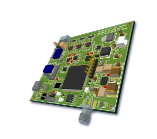
From a system integration perspective, the MBC‑SUPER is built for OEM and laboratory setups where size and simplified wiring matter. The module measures only 2.53 × 2.57 × 0.65 inches and weighs approximately 0.2 lb, making it easy to embed inside optical transceivers, benchtop instruments, or rack‑mounted chassis. Typical power requirements are +15 V and –15 V DC, with modest current consumption (around 145 mA on the positive rail and 80 mA on the negative rail). This is compatible with standard laboratory supplies and many existing instrument backplanes.
Modulator Bias Controller - Tunable
Specifications
| Product Type: | MBC |
|---|---|
| Modulation Type: | QPSK |
| Detector Input Power: | -10 dBm |
| Locking Slope: | Positive, Negative |
| Locking Mode: | Null, Peak Positions |
| Photodetector Type: | External |
| Tunability: | Tunable |
| Optical Wavelength Range: | 1000 - 1650 nm |
| Bias Voltage: | -12 to +12 V |
| Null Mode Extinction Ratio (Max): | 40 dB |
| Amplitude: | 20 to 250 mV |
| Pilot Tone Frequency: | 5/10 kHz |
| DC Positive Power Voltage: | 15 V |
| DC Negative Power Voltage: | -15 V |
| DC Positive Power Current: | 145 mA |
| DC Negative Power Current: | 80 mA |
| Operating Temperature: | 0 to +50 °C |
| Storage Temperature: | -40 to +85 °C |
| Dimension: | 2.53 x 2.57 x 0.65 inches |
| Weight: | 0.2 lb |
Got questions about specs? Use the inquiry form to ask.
 Download Data Sheet

Features
- Advanced Modulator Bias Control for MZ Modulators – Precisely locks the operating point of Mach-Zehnder (MZ) modulators at Quad+, Quad-, Null, or Peak on the transfer curve for optimum linearity or maximum extinction.
- User-Selectable Locking Modes & Slopes – Flexible selection of locking mode (Null, Peak, +Quadrature, –Quadrature) and locking slope (positive or negative) via an intuitive GUI, making it suitable for a wide variety of analog and digital modulation schemes.
- Dual Operation Modes for Fast Setup – Supports dedicated Calibration Mode to scan and characterize the modulator response, and Locking Mode for stable long-term bias control, plus a Calibration Off option to speed system deployment.
- High Extinction Ratio in Null Mode – Provides up to 40 dB Null Mode extinction ratio (limited by the modulator), enabling deep suppression of the optical carrier for advanced modulation formats and high dynamic range applications.
- Pulse Mode Optimized for Dense Pulse Applications – Integrated pulse mode improves Null locking accuracy in pulsed systems and dense pulse trains, significantly enhancing extinction and stability over conventional CW-only bias controllers.
- Fine Pilot Tone Control for Minimal System Impact – Adjustable pilot tone modulation depth and pilot tone amplitude (0–250 mV Vpp), with selectable pilot tone frequencies of 1, 5, 10, or 40 kHz, to minimize interference with data channels while maintaining robust lock.
- Manual Mode & Pilot Tone Disable – Pilot tone can be stopped and the unit placed into manual bias control mode when required by system constraints, providing maximum flexibility for custom experiments or legacy systems.
- Integrated & External Photodetector Support – Comes with an optional pigtailed photodiode (PD) input and provides access for external photodetectors, allowing easy integration with existing monitoring hardware or wavelength-specific detectors.
- Wide Optical Wavelength Range – Standard operation over 1000–1650 nm; with an appropriate external photodiode the wavelength range can be further expanded to support specialty sources and non-standard bands.
- Broad Bias Voltage Range for Various Modulators – Offers a –12 V to +12 V single‑ended bias output range, compatible with a wide array of LiNbO₃ and other integrated optical modulators used in telecom, test & measurement, and sensing.
- Low Optical Power Operation – Designed for detector input powers from –25 dBm to –10 dBm, supporting low‑power optical links and minimizing the need for additional optical amplification or high-power sources.
- Compact OEM-Friendly Footprint – Ultra-compact module size of 2.53″ × 2.57″ × 0.65″ and lightweight design (~0.2 lb) ideal for space‑constrained OEM systems, rack-mounted instruments, and portable platforms.
- PC-Based GUI with Multi-Unit Control – Standard USB Type‑B interface with a powerful graphical user interface (GUI) for configuring operation modes, pilot tone parameters, and monitoring status. The GUI supports multi‑unit control for scalable multi‑channel systems.
- Flexible Communication Interfaces – In addition to USB, optional RS232 DB9 or RS232 Flywire (RS232FW) interfaces are available, simplifying integration into existing control architectures and embedded controllers.
- Stable Digital Control Architecture – Digital signal processing enhances bias stability, reduces noise and required pilot tone amplitude, and improves long-term drift performance compared with purely analog bias control schemes.
- Dedicated System Configuration Support – Easily integrates into typical setups using a 1–5% tap coupler, photodetector, and modulator (see system configuration), providing a complete ready-to-use bias control solution for high-speed optical links.
- Robust Operating Temperature Range – Specified for 0–40 °C operation and –40–85 °C storage, suitable for controlled lab environments, production test racks, and tightly regulated field systems.
Applications
- Automatic bias control for LiNbO3 Mach-Zehnder intensity modulators Maintain a stable operating point at Quad+, Quad−, Null, or Peak to prevent drift in electro‑optic modulators used in high‑performance optical links.
- Coherent and high‑speed optical communication systems Stabilize modulator bias in 10G to 400G+ coherent and IM/DD links, reducing signal distortion, penalty, and BER in long‑haul, metro, and data‑center interconnects.
- Pulse mode operation for dense optical pulse applications Use the dedicated pulse mode to achieve accurate Null locking with low duty‑cycle or closely spaced optical pulses in time‑division multiplexing, optical ranging, and pulsed laser links.
- Analog and RF‑over‑fiber links Bias control for modulators in CATV, satellite IF, microwave, and millimeter‑wave photonic links to maximize linearity and carrier‑to‑noise ratio over temperature and time.
- Quantum communication and quantum optics experiments Precisely lock Mach‑Zehnder interferometers used for phase encoding, entanglement distribution, and quantum key distribution where interferometer stability is critical.
- Photonic test and measurement setups Integrate the controller into laboratory testbeds to remove bias drift when characterizing high‑speed modulators, drivers, and optical components in R&D environments.
- Optical signal generation and waveform shaping Maintain stable quadrature or Null bias for generation of advanced modulation formats, optical pulses, and arbitrary optical waveforms in photonic signal processing systems.
- Optical sensing and interferometric measurement Use in fiber interferometers, fiber gyroscopes, and other phase‑sensitive sensors where a Mach‑Zehnder modulator is used for modulation or readout and bias stability directly affects sensitivity.
- LiDAR, ranging, and time‑of‑flight systems Improve extinction ratio and stability of modulated laser pulses for coherent and direct‑detection LiDAR, where dense pulse trains require robust Null locking.
- Stabilization of optical carriers for microwave photonics Keep the modulator at optimal bias to generate low‑noise optical sidebands and stable optical carriers for microwave and millimeter‑wave photonic signal generation and distribution.
- Secure optical links and encryption systems Ensure long‑term bias stability in systems using Mach‑Zehnder modulators for optical encryption, scrambling, or data‑hiding, minimizing information leakage due to drift.
- DWDM and multi‑channel optical transmitters Deploy one controller per modulator in dense wavelength‑division multiplexing transmitters to maintain uniform performance and extinction ratio across many channels.
- OEM integration in compact photonic modules Take advantage of the small footprint (2.53" × 2.57" × 0.65") and flexible interfaces (USB, optional RS‑232) for integration into transceiver modules, benchtop instruments, or rack‑mount systems.
- Long‑term unattended operation in field systems Use the digital locking scheme to compensate for temperature changes, aging, and vibration in deployed optical links and sensor systems with minimal maintenance.
- Research on nonlinear and ultrafast optics Maintain precise interferometer bias while exploring nonlinear effects, ultrafast pulse modulation, and time‑resolved experiments requiring stable transmission points.
- Educational photonics laboratories Provide students with a robust, easy‑to‑use bias control module with GUI control for demonstrating Mach‑Zehnder operation, bias points, and extinction ratio without manual re‑tuning.
- Systems requiring external or internal photodetector monitoring Use the included pigtailed photodiode or connect an external detector for flexible monitoring topologies, 1–5% tap couplers, and customized feedback paths.
- Environments with low available optical power Operate reliably with detector input power from −25 dBm to −10 dBm over a broad wavelength range (1000–1650 nm), covering O‑, C‑, and L‑band communication windows.
- Systems needing flexible pilot tone control Optimize performance with adjustable pilot tone amplitude and modulation depth, and selectable frequencies (1, 5, 10, 40 kHz) to avoid interference with data or RF spectra.
- Multi‑channel and multi‑unit control setups Leverage the multi‑unit GUI capability to control several MBC‑SUPER modules simultaneously in complex transmitters, coherent engines, and multi‑path interferometric systems.
Frequently Asked Questions
What is the MBC-SUPER Modulator Bias Controller and what does it do?
How does the MBC-SUPER bias controller lock the modulator at quadrature, null, or peak?
What is special about the pulse mode in the MBC-SUPER for null locking in dense pulse applications?
What are the optical input power and wavelength requirements for the MBC-SUPER?
How do I physically integrate the MBC-SUPER into my Mach–Zehnder modulator setup?
What interfaces and control options does the MBC-SUPER provide (USB, RS-232, GUI, multi‑unit control)?
What are the mechanical, environmental, and ordering details for the MBC-SUPER?
Got more questions? Use the inquiry form to ask the supplier directly.
Similar Products


Your inquiry has been received.
Create an account by adding a password
Why create an account?
- Auto-complete inquiry forms
- View and manage all your past messages
- Save products to your favorites
- Close your account anytime — no hassle