


Description
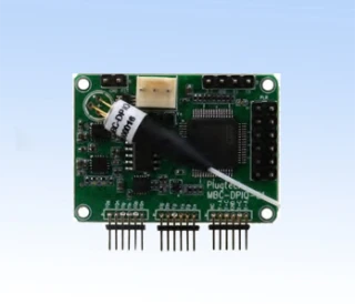
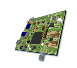
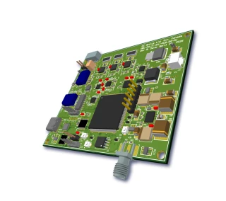
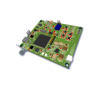
The Precision Ditherless Bias Controller (MBC-PDBC) is an OEM-grade, standalone electronic module designed to provide ultra-stable, closed‑loop bias control for optical modulators and related photonic components. Optimized for use with Mach–Zehnder (MZ) modulators and Fabry–Perot fiber loop-back configurations, this controller combines automatic locking, ditherless operation, and manual bias tuning in a compact footprint. It is ideal for advanced fiber‑optic communication systems, coherent detection setups, LiDAR, test and measurement platforms, and laboratory R&D where precise and long‑term stable modulator bias control is essential.
Unlike traditional bias controllers that rely solely on continuous dithering, the MBC-PDBC employs a hybrid approach. It first uses a low‑frequency pilot tone to rapidly and accurately locate the quadrature (Quad) operating point of the modulator. Once Quad is reached, the controller switches into true ditherless mode, maintaining the operating point with high accuracy without further modulation on the optical signal. This architecture significantly improves signal integrity and minimizes added noise or spectral artifacts, which is particularly valuable in high‑speed digital transmission, analog RF‑over‑fiber links, and precision interferometric measurements.
The controller supports an input optical power range from –30 dBm to –10 dBm and achieves a typical locking accuracy of about 2 degrees, ensuring highly repeatable and stable biasing even under drift conditions caused by temperature changes, device aging, or environmental perturbations. A bias output range of –10 V to +10 V provides compatibility with a wide variety of LiNbO3 and other integrated optical modulators, as well as with tunable Fabry–Perot filters and similar devices requiring precision voltage biasing. When the modulator drifts out of the specified operating range, the bias controller automatically pulls the bias back to the desired working point, preventing performance degradation and system downtime.
For system designers and integrators, the MBC-PDBC offers both automated and manual control modes. In automatic mode with pilot tone enabled, the unit locks to quadrature and then continues operation in ditherless closed loop for maximum stability and low noise. The pilot tone can be disabled, allowing a purely manual mode where the user sets the desired operating point via an external control voltage. This flexibility makes the module suitable for applications that require custom bias points (e.g., minimum or maximum transmission, or user‑defined phases), as well as for experimental setups where frequent optimization and tuning are needed.
The board integrates two on‑board photodiodes to monitor the optical signal, simplifying system architecture and reducing the need for external detection hardware. A user port is provided for applying an external reference or tuning voltage in manual mode, enabling fine control and easy integration into larger control systems or automated test benches. The locking slope can be configured via an on‑board jumper, allowing adaptation to different modulator characteristics and system response requirements. Additionally, an alarm LED indicates overtuning or abnormal bias conditions, providing immediate visual feedback for diagnostics and system health monitoring.
With typical supply requirements of ±12 V (compatible with ±10 V to ±15 V rails) and modest current draw, the MBC-PDBC is straightforward to power from standard laboratory or OEM system supplies. Operating over a 0–70 °C temperature range and housed in a compact 3.3 × 2.2 × 0.5 inch PCB module, it is well suited for both benchtop setups and space‑constrained embedded photonic subsystems. The combination of high dynamic range, fast response, and ditherless locking performance positions this controller as a robust solution for modern optical networks, coherent modulation formats, and precision optical metrology where stable, low‑noise modulator biasing is a critical requirement.
Precision Ditherless Bias Controller
Specifications
| Product Type: | PDBC |
|---|---|
| Modulation Type: | DQPSK |
| Detector Input Power: | -10 dBm |
| Locking Slope: | Positive, Negative |
| Locking Mode: | Quad+, Quad-, Null, Peak Positions |
| Photodetector Type: | Unspecified |
| Tunability: | Tunable |
| Input Signal Current: | 0.1×10^-3 to 0.1 mA |
| Input Optical Power: | -30 to -10 dBm |
| Locking Accuracy: | 1.6–2 degrees |
| DC Bias Voltage: | -10 to +10 V |
| Modulation Depth (calibration/reset Only): | 6 % |
| Pilot Tone Frequency: | 1 kHz |
| Positive Power Supply: | +10 to +15 V (typ. 12 V) |
| Negative Power Supply: | -10 to -15 V (typ. -12 V) |
| Positive Supply Current: | 120 mA |
| Negative Supply Current: | 90 mA |
| Operating Temperature: | 0 to 70 °C |
| Storage Temperature: | -40 to 80 °C |
| Dimensions (L×W×H): | 3.3 × 2.2 × 0.5 inch |
Got questions about specs? Use the inquiry form to ask.
 Download Data Sheet

Features
- Ditherless bias control with auto‑quad locking – Automatically drives the modulator to the precise quadrature point using a pilot tone, then switches to true ditherless operation for ultra‑stable bias locking without adding modulation noise to the signal path.
- High locking accuracy and stability – Typical locking accuracy of ~1.6–2 degrees ensures consistent operating point, minimizing signal distortion and drift in demanding analog and digital fiber‑optic links.
- Wide dynamic range input – Supports input signal currents from 0.1 μA to 0.1 mA and optical power from –30 dBm to –10 dBm, enabling reliable operation with a broad range of photodiodes and input signal levels.
- Broad DC bias voltage range – Provides a programmable DC bias output from –10 V to +10 V, compatible with most LiNbO₃ Mach‑Zehnder modulators and other electro‑optic devices.
- Compatible with multiple device types – Optimized for Mach‑Zehnder (MZ) intensity modulators and also suitable for Fabry‑Perot tunable filters and other fiber‑optic components requiring precise bias or cavity control.
- Fast response for dynamic environments – Closed‑loop feedback and pilot‑tone calibration support rapid re‑locking when the operating point drifts outside the specified range, maintaining stable performance under changing temperature or optical power conditions.
- Selectable manual and automatic operating modes – Users can disable the pilot tone and operate in manual mode, applying an external control voltage to lock the bias at any desired working point (not only quadrature).
- On‑board tuning and external reference input – Includes a user port for applying an external tuning voltage in manual mode, and offers an optional external reference voltage input (factory‑specified) for customized control schemes.
- Configurable locking slope – Locking polarity/slope can be inverted via an on‑board jumper, simplifying integration with different modulator transfer functions and system architectures.
- Integrated dual photodiodes – Two built‑in photodiodes (PD‑1 and PD‑2) enable flexible monitoring and feedback configurations, reducing the need for external detector hardware and simplifying system wiring.
- Low‑impact pilot tone – Pilot tone frequency around 1 kHz and modest modulation depth (~6% during calibration/reset only) ensure minimal impact on the main data or analog signal; pilot tone is automatically turned off during normal ditherless operation.
- Over‑tuning protection with status indication – Built‑in alarming LED warns of overtuning or out‑of‑range conditions, helping users quickly diagnose bias drift or mis‑configuration during setup and operation.
- Robust power supply compatibility – Operates from symmetric ±10 V to ±15 V supplies (typ. ±12 V), with low supply currents (approx. +120 mA / –90 mA), making it suitable for OEM and embedded system designs.
- Wide operating temperature range – Qualified for 0 °C to +70 °C operation and –40 °C to +80 °C storage, supporting deployment in lab, production, and many field environments.
- Compact OEM form factor – Small footprint of approximately 3.3 × 2.2 × 0.5 inches allows easy integration into optical transmitters, test setups, and system racks with limited board space.
- Improved link linearity and SNR – By locking the modulator at the optimal operating point without continuous dithering, the controller enhances system linearity, reduces residual AM‑to‑PM conversion, and improves overall signal‑to‑noise ratio in high‑performance optical links.
- Ideal for advanced fiber‑optic applications – Suited for microwave‑over‑fiber links, CATV and RFoF systems, coherent communication setups, optical test and measurement benches, and any application requiring long‑term stable modulator bias control.
Applications
- Automatic Bias Control of LiNbO3 Mach–Zehnder Modulators – Maintains the modulator at the precise quadrature (Quad) point for high‑linearity intensity modulation in analog and digital fiber‑optic links, minimizing distortion and maximizing extinction ratio in CATV, RF‑over‑fiber, and broadband transmission systems.
- Ditherless Bias Stabilization in Coherent and High‑Speed Digital Optics – Provides stable, low‑noise bias control for coherent transmitters, QPSK/QAM formats, and high‑baud‑rate NRZ/PAM systems where conventional dithering tones would interfere with advanced modulation and DSP algorithms.
- Bias Control for Analog RF‑over‑Fiber and Microwave Photonics Links – Optimizes linearity in intensity modulators used for transport of RF, microwave, and millimeter‑wave signals, supporting applications in radar remoting, base‑station fronthaul, satellite links, and distributed antenna systems by locking at the optimal working point without adding pilot‑tone distortion.
- Stabilization of Fabry–Perot and Tunable Optical Filters – Controls the bias of Fabry–Perot tunable filters in loop‑back configurations to lock the cavity to a desired wavelength or resonance peak, improving stability in wavelength selection, optical channel equalization, and narrowband filtering for DWDM systems.
- Bias Control for Optical Intensity Modulators in Test and Measurement Setups – Ensures repeatable bias conditions in laboratory setups involving MZ modulators used as optical shutters, power controllers, or amplitude modulators, providing consistent operating points for BER testing, eye‑diagram measurements, and component characterization.
- Long‑Term Drift Compensation in Environmental Test Racks – Compensates for temperature‑induced and aging‑related drift of electro‑optic modulators in burn‑in ovens, environmental chambers, and life‑test stations, maintaining a constant bias point from 0°C to 70°C for reliable, automated characterization.
- OEM Integration in Fiber‑Optic Transmitters and Subsystems – Compact OEM module format enables easy integration into custom transmitters, optical front‑ends, and photonic integrated assemblies, adding robust, closed‑loop bias stabilization without requiring a full custom electronics design.
- Stabilized Intensity Control in Fiber‑Laser and CW Laser Systems – When used with an MZ modulator and the on‑board photodiodes, the controller can maintain constant output power or a fixed operating point for CW lasers in precision illumination, sensing, and metrology systems where power fluctuations must be minimized.
- Closed‑Loop Power Control in Optical Sensing and Interferometric Setups – Enhances performance of fiber‑optic interferometers, sensor readout units, and coherent detection systems by stabilizing the intensity modulator bias, reducing noise and improving signal‑to‑noise ratio in interferometric measurements.
- R&D on Advanced Modulation Formats and Photonic Circuits – Ideal for research labs developing new LiNbO3 or integrated‑photonic modulators (e.g., silicon photonics MZ structures) where fast, tunable, and accurate bias control is required to explore different working points and modulation schemes.
- Manual Bias Tuning and Characterization of Electro‑Optic Devices – Manual‑mode operation with external control voltage input allows users to sweep or set custom bias points of modulators and tunable components, useful for transfer‑function measurements, Vπ extraction, and device comparison in development environments.
- High‑Stability Optical Communication Links for Metrology and Timing – Supports low‑noise intensity modulation in precision time‑transfer systems, frequency‑comb distribution, and optical reference links where ditherless, high‑accuracy bias control preserves signal integrity over long distances.
- Bias Control in Multi‑Channel and Polarization‑Diverse Modulator Arrays – Multiple controllers can be deployed to independently lock several MZ arms or polarization channels at their optimal working points, supporting complex transmitters, polarization multiplexing, and IQ modulator configurations.
- Failsafe Operation with Overtuning Alarm Indication – The built‑in alarm LED for overtuning helps system integrators quickly detect out‑of‑range or mis‑biased states in production systems, improving reliability and simplifying diagnostics in field‑deployed optical equipment.
Frequently Asked Questions
What is the OZ Optics MBC-PDBC Precision Ditherless Modulator Bias Controller and what does it do?
How does the ditherless bias control and pilot tone mode work on the MBC-PDBC?
Which modulators and applications are compatible with the MBC-PDBC bias controller?
What are the key electrical and optical specifications of the MBC-PDBC bias controller?
Can the MBC-PDBC be used in manual bias mode, and how is the bias point adjusted?
How do I connect the MBC-PDBC to a Mach–Zehnder modulator or a Fabry–Perot tunable filter?
What safety and status features does the MBC-PDBC provide, such as drift correction and alarms?
Got more questions? Use the inquiry form to ask the supplier directly.
Similar Products


Your inquiry has been received.
Create an account by adding a password
Why create an account?
- Auto-complete inquiry forms
- View and manage all your past messages
- Save products to your favorites
- Close your account anytime — no hassle