


Description
Mini Modulator Bias Controller (MBC) – Compact, High‑Stability Bias Control for MZ Modulators
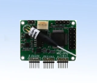
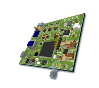
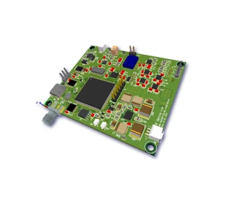
The Mini Modulator Bias Controller (MBC) is a compact, full‑function OEM solution designed to provide precise, long‑term stable bias control for single Mach–Zehnder (MZ) optical modulators in demanding fiber‑optic systems. Engineered as a miniature version of larger rack‑mount and benchtop controllers widely used in research and industry, this board‑level MBC integrates bias generation, pilot‑tone lock detection, and photodetection on a low‑profile PCB. It is ideal for OEM integration into transmitters, test setups, and advanced photonic subsystems where space, power consumption, and ease of deployment are critical.
At the core of the Mini MBC is accurate tracking of the MZ modulator’s transfer function, as illustrated by the standard sine‑squared working curve. By applying a low‑frequency pilot tone and monitoring the detected optical power, the controller continuously senses the operating point and automatically adjusts the bias voltage to maintain lock. This closed‑loop control effectively compensates for temperature drift, device aging, and optical power fluctuations, ensuring stable operation around the desired working point over time. Compared to manually adjusted bias supplies or open‑loop drivers, the Mini MBC significantly improves system uptime and measurement repeatability in real‑world environments.
The controller supports the most commonly used operating points for intensity modulation: positive‑slope quadrature (Quad+), negative‑slope quadrature (Quad‑), minimum transmission (Null), and maximum transmission (Peak). User‑selectable locking slopes and modes are set via onboard jumpers, allowing the same hardware to support diverse system architectures—from linear analog links that benefit from quadrature bias, to on–off keying (OOK) and extinction‑sensitive digital links that require accurate null or peak locking. This versatility matches or exceeds that of many larger bias controllers used in advanced coherent and intensity‑modulated systems, while offering a much smaller footprint for integration into OEM hardware.
Designed for telecom and near‑IR photonics, the Mini Modulator Bias Controller operates over a wide optical wavelength range of 1000–1650 nm, compatible with standard LiNbO3 and related modulators as well as many integrated photonic platforms. The included pigtailed photodetector captures a small fraction of the optical output via a coupler (typical 1–2%), providing the feedback signal necessary for bias locking without significantly impacting the main channel power. For systems that already incorporate dedicated monitoring taps, the controller also allows the use of an external photodetector, offering additional flexibility in system layout and detection sensitivity.
In null mode, the controller supports a high extinction ratio, typically up to 40 dB under appropriate modulator conditions and coupler configurations. This enables precise suppression of the “off” state in digital intensity modulation and improves signal‑to‑noise ratio in applications such as optical sensing, RF‑over‑fiber links, and advanced modulation formats. Under quadrature operation, the MBC maintains the bias around the linear region of the transfer curve, essential for analog and RF photonic links where distortion, intermodulation products, and gain flatness are critical performance metrics. The typical pilot‑tone frequencies of 1 kHz (for QUAD) and 2 kHz (for NULL) are chosen to be well outside most data and RF bands, simplifying filtering and preventing interference with the main signal path.
From an electrical standpoint, the Mini MBC provides a bias voltage range of approximately −10 V to +10 V with up to 100 mA bias current capability, allowing it to drive a wide variety of MZ modulators with different half‑wave voltages (Vπ) and bias network requirements. The modulation depth of the pilot tone is kept low—on the order of 1–2% at quadrature and about 0.1% in null mode—so that the impact on the optical signal is minimal while still enabling accurate error‑signal detection. This balances the need for robust locking with the requirement not to degrade link performance or measurement precision in high‑end photonics setups.
The board incorporates two primary operating modes: calibration mode and locking mode. In calibration mode, the user can scan or adjust the bias to characterize the modulator response, locate the desired operating point, and verify optical power levels during setup. Once the system is configured, locking mode is engaged to maintain the selected bias point automatically. A dedicated “calibration off” capability streamlines transitions into locking mode and speeds up system commissioning, which is especially valuable for OEM customers assembling complex optical modules or for laboratories frequently reconfiguring testbeds.
Mini Modulator Bias Controller
Specifications
| Product Type: | MBC-MINI |
|---|---|
| Modulation Type: | Other |
| Detector Input Power: | -10 dBm |
| Locking Slope: | Positive, Negative |
| Locking Mode: | Quad+, Quad-, Null, Peak Positions |
| Photodetector Type: | External |
| Tunability: | Unspecified |
| Detector Input Power Range: | -30 to -10 dBm |
| Optical Wavelength Range: | 1000–1650 nm |
| Bias Voltage: | -10 to +10 V |
| Bias Current: | up to 100 mA |
| Null Mode Extinction Ratio: | 25 to 40 dB |
| Locking Slope: | Positive or Negative |
| Locking Mode: | Quad+ (Quad-) or Null (Peak) |
| Pilot Tone Modulation Depth (QUAD): | 1–2 % |
| Pilot Tone Modulation Depth (Null): | 0.1 % |
| Pilot Tone Frequency (QUAD): | 1000 Hz |
| Pilot Tone Frequency (NULL): | 2000 Hz |
| Positive Power Voltage: | 11.5–12.5 V |
| Negative Power Voltage: | -12.5 to -11.5 V |
| Positive Power Current: | 60 mA |
| Negative Power Current: | 40 mA |
| Operating Temperature: | 0–70 °C |
| Storage Temperature: | -40–85 °C |
| Dimensions: | 3.1 x 1.6 x 0.65 inch |
| Weight: | 0.2 lb |
| Board Length: | 3.050 in (77.47 mm) |
| Board Width: | 1.600 in (40.64 mm) |
| Board Height: | 0.65 in |
| Mounting Hole Diameter: | 0.110 in (2.79 mm) |
Got questions about specs? Use the inquiry form to ask.
 Download Data Sheet

Features
- Compact Modulator Bias Controller – Mini OEM Design
Ultra-compact footprint of 3.1" x 1.6" x 0.65" (0.2 lb), ideal for integration into space‑constrained photonic systems and OEM platforms. - Full Bias Control for Single Mach‑Zehnder Modulators
Designed to lock the operating point of a single MZ modulator at Quad+, Quad‑, Null, or Peak on the transfer characteristic, ensuring stable and repeatable modulation. - User‑Selectable Locking Slope & Locking Mode
Flexible jumper‑selectable operation with independent choice of locking slope (positive or negative) and locking mode (Quad+/Quad‑ or Null/Peak) to match a wide range of modulation formats and system requirements. - Two Distinct Operation Modes: Calibration & Locking
Built‑in calibration mode simplifies initial setup and optimization, while locking mode maintains long‑term bias stability against drift due to temperature and aging. - Calibration‑Off Function for Fast System Setup
Calibration off mode allows quick transition from setup to normal locked operation, reducing commissioning time in lab and production environments. - Wide Optical Wavelength Range
Supports detector input from 1000 to 1650 nm, covering O‑, E‑, S‑, C‑, and L‑bands, compatible with most telecom and test & measurement modulators. - Optimized for Low Optical Power Levels
Operates with detector input power from ‑30 dBm to ‑10 dBm (at minimum attenuation), supporting systems using 1–2% tap couplers without requiring high‑power sources. - High Extinction Ratio in Null Mode
Achieves up to 40 dB null‑mode extinction ratio (25 dB typical), preserving the intrinsic extinction of high‑performance LiNbO₃ modulators for advanced digital and analog links. - Stable Pilot‑Tone Based Bias Control
Uses internal pilot tones with optimized frequencies and depths:- Quad mode: 1–2% modulation depth at ~1 kHz
- Null mode: ~0.1% modulation depth at ~2 kHz
- High Output Bias Capability
Provides up to ±10 V bias voltage and up to 100 mA bias current, suitable for driving a broad range of LiNbO₃ intensity modulators and other electro‑optic devices. - External or Integrated Photodetector Support
Includes a pigtailed photodetector and also offers access for an external photodetector, giving system designers flexibility in detector placement, wavelength range, and responsivity. - Stand‑Alone Hardware – No Computer Required
Fully stand‑alone bias controller; all configuration via on‑board jumpers and connections. No PC software or digital interface is needed, simplifying deployment and improving reliability. - Dual ±12 V Supply Operation with Low Power Consumption
Operates from standard +12 V / ‑12 V rails with typical currents of ~60 mA (positive) and ~40 mA (negative), enabling easy integration into existing analog or RF photonics racks. - Improved Long‑Term Stability and Reduced Drift
Automatically compensates for environmental effects such as temperature changes, component aging, and optical power fluctuations, maintaining optimal bias over long operating times. - Supports High‑Performance Analog & Digital Links
Suitable for CATV, RF‑over‑fiber, microwave photonics, coherent and intensity‑modulated systems, where stable quadrature or null operation is critical for linearity and signal integrity. - Easy Mechanical Integration
Standardized board format with four mounting holes (Ø0.110"), clearly defined outline (approx. 3.05" x 2.90" maximum), and low profile for convenient panel or chassis mounting. - Wide Operating Temperature Range
Rated for 0 to +70 °C operating and ‑40 to +85 °C storage, suitable for laboratory setups as well as controlled industrial environments. - Reliable OEM Solution with Field‑Proven Architecture
Part of a widely deployed Modulator Bias Controller (MBC) family, offering a compact, cost‑effective option without compromising the core locking performance used in larger systems.
Applications
- Bias control for LiNbO3 and InP Mach–Zehnder modulators in coherent and direct-detection fiber optic links
- Stabilization of quadrature operating point (Quad+/Quad−) for linear optical modulation in high-speed digital communication systems
- Null and peak locking for intensity-modulated optical transmitters requiring maximum extinction ratio and high on/off contrast
- Automatic bias control in analog RF-over-fiber links to minimize distortion and maintain linearity over temperature and time
- DWDM and CWDM optical transmitters where stable modulator bias is required for multiple wavelength channels
- Coherent communication systems using external modulators that must be locked at quadrature for optimal I/Q constellation stability
- Test and measurement setups for characterizing LiNbO3, InP, and silicon photonic modulators in R&D labs and production lines
- Long‑term drift compensation of modulator bias due to temperature variations, aging, and polarization changes in fiber networks
- Stabilized optical amplitude modulation for metrology systems, optical sensing, and interferometric measurements
- Bias control in high‑speed pulsed laser and CW laser modulation for time‑resolved spectroscopy and optical sampling
- Automatic lock of integrated silicon photonics modulators in PIC-based transmitters and photonic integrated systems
- Maintaining optimum extinction ratio in external modulation systems for high bit‑rate telecom and datacom links (10G, 40G, 100G+)
- Optical arbitrary waveform generation and pulse shaping where stable quadrature bias is critical to waveform fidelity
- Satellite and defense optical communication links requiring robust, stand‑alone bias control without a host computer
- CATV and broadband analog video distribution over fiber to minimize CSO/CTB and improve signal quality via precise bias locking
- Microwave photonics experiments for RF signal processing and frequency up/down conversion using Mach–Zehnder modulators
- Quantum optics and quantum communication setups using modulators for phase and amplitude control of single photons or weak coherent states
- Stabilized interferometers and fiber sensors employing MZ structures that require fixed quadrature or null operation
- Educational and demonstration systems illustrating MZ modulator transfer functions, quadrature locking, and bias control techniques
- Field‑deployable OEM transmitter modules where compact, low‑profile modulator bias control is required without PC control
- Integration with external photodetectors or built‑in pigtailed photodiodes for flexible feedback topologies in OEM boards
- Closed‑loop bias stabilization using low modulation depth pilot tones in the 1 kHz–2 kHz range without degrading system SNR
- Upgrading legacy external modulator systems that currently use manual bias adjustment to fully automatic bias control
- Maintaining consistent output power and eye diagram quality in high‑speed optical transmitters during extended continuous operation
Frequently Asked Questions
What is the Mini Modulator Bias Controller (MBC) and what does it do?
Which modulators and wavelengths are compatible with this Modulator Bias Controller?
How do the locking modes (Quad+, Quad−, Null, Peak) and slopes work on the Mini MBC?
What are the optical power and photodetector requirements for the Mini Modulator Bias Controller?
What power supply and electrical conditions are required to operate the Mini MBC?
What extinction ratio and performance can I expect in Null mode?
What are the mechanical dimensions, operating temperature, and integration options?
Got more questions? Use the inquiry form to ask the supplier directly.
Similar Products


Your inquiry has been received.
Create an account by adding a password
Why create an account?
- Auto-complete inquiry forms
- View and manage all your past messages
- Save products to your favorites
- Close your account anytime — no hassle