
Description
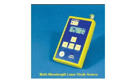
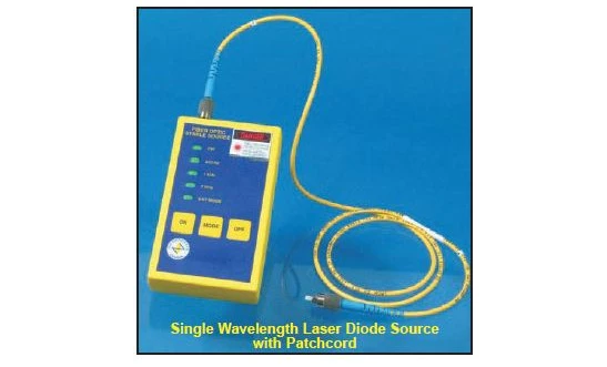
The Laser Diode Source – Fiber Optic is a versatile, precision light source engineered for professionals who require reliable single or multi-wavelength outputs for testing, installation, and maintenance of fiber optic networks. Designed for use across telecommunication, datacom, and fiber sensing environments, this compact source delivers stable optical power in continuous wave (CW) mode as well as user-selectable waveform modulation. Its broad wavelength availability makes it well suited for verifying system performance in FTTX/PON architectures, short-haul links, and lab test benches where accurate insertion loss and attenuation measurements are critical.
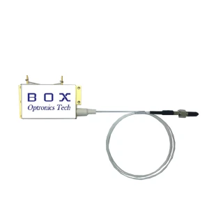
Built for flexibility in real-world field and laboratory workflows, this laser source is offered in both receptacle and pigtail configurations to match a wide range of fiber and connector standards. Receptacle-style units accommodate multiple connector formats to support existing test setups, while pigtail-style versions are available with polarization-maintaining, singlemode, or multimode fibers. This allows users to match the source to their specific application, from polarization-sensitive measurements and coherent systems to standard multimode LAN and data center links. For polarization-maintaining versions, PANDA-style fibers are typically used to provide robust, repeatable polarization performance across demanding environments.
To support a broad variety of test scenarios, the standard configuration provides stable CW output as well as internal modulation at commonly used frequencies such as 270 Hz, 1 kHz, and 2 kHz. These modulation options are particularly useful for fiber identification in live bundles and for distinguishing test signals from background light or traffic. Selected models, such as the FOSS-2N variants, also offer user-selectable preset power levels controlled directly from the keypad, allowing quick adaptation to different fiber types, link budgets, or sensitivity requirements of downstream measurement instruments.
The unit’s ergonomic and rugged design is optimized for field deployment. A clear front-panel display provides immediate visibility of key operating parameters, while a low battery indicator ensures users are alerted well before power levels become critical. Operation from standard AA batteries offers convenience and portability for on-site work, and an optional external AC/DC adapter can be used in the laboratory or on extended jobs where continuous operation is required. The compact form factor enables easy transport in toolkits or instrument cases without sacrificing output stability or usability.
Stability and repeatability are central to the design of this fiber optic laser source. For applications at 1300 nm and 1550 nm, optional optical isolators can be integrated to further minimize back-reflection–induced power fluctuations, improving measurement confidence in high-precision test environments. Angled connectors are recommended for enhanced return loss and overall stability, aligning the device with industry best practices for singlemode network testing and qualification. For users who require even higher stability and long-term thermal control, this platform is complemented by highly stable source variants that incorporate temperature regulation and additional isolation measures.
Typical use cases include insertion loss and attenuation measurements for certifying links, splicing and connectorization verification during installation, fiber identification using internal modulation in complex cable routes, and end-to-end testing of short and medium-length links. The combination of multi-wavelength capability, support for different fiber types, and selectable modulation frequencies makes the Laser Diode Source – Fiber Optic an efficient and cost-effective tool for technicians, engineers, and quality assurance teams working across modern optical networks and test labs.
Fiber Optic Laser Diode Source - Single or Multi-Wavelength
Specifications
| Laser Type: | Continuous Wave (CW) |
|---|---|
| Fiber Type: | Single Mode |
| Wavelength: | 1550 nm |
| Output Power: | 1 mW |
| Fiber Core Diamater: | 4 um |
| Fiber Cladding Diameter: | 125 um |
| Product Type: | Fiber Optic Laser Diode Source |
| Wavelength Options: | 635, 655, 670, 685, 780, 810, 830, 850, 980, 1310, 1490, 1550, 1625 nm |
| Output Power: | 0.8 to 1 mW |
| Fiber Type: | 4/125 µm core/cladding singlemode fiber |
| Receptacle (37517): | FC/APC, angled |
| Receptacle (36708): | Super FC/PC |
| Operating Mode: | Continuous wave (CW) and waveform (pulse) modulation |
| Internal Modulation Frequencies: | 270 Hz, 1 kHz, 2 kHz |
| Power Levels (model FOSS-2N): | 4 preset user-selectable levels |
| Power Supply: | 2 × AA batteries or optional 5 V AC/DC adapter |
| Connector Compatibility: | Wide range of connector receptacles |
| Fiber Output Options: | Polarization-maintaining, singlemode, or multimode |
| Auto Turn-off: | User selectable |
| Battery Indicator: | Low battery indicator on front panel |
Got questions about specs? Use the inquiry form to ask.
 Download Data Sheet

Features
- Single or Multi‑Wavelength Operation: Available as single or multi-wavelength laser diode sources, ideal for versatile fiber optic testing across multiple network windows (e.g., 635 nm, 850 nm, 1300 nm, 1310 nm, 1490 nm, 1550 nm).
- Continuous Wave (CW) and Modulated Output: Supports stable CW output and internal waveform modulation at 270 Hz, 1 kHz, and 2 kHz for insertion loss, attenuation, and fiber identification measurements.
- Wide Range of Connector Receptacles: Configurable with popular connector types (FC/PC, FC/APC, SC, SC/APC, LC, ST, and others) to ensure compatibility with existing fiber networks and test setups.
- Optional Output Power Adjustment: Selectable preset output power levels (e.g., via front keypad on FOSS‑2N) allow precise control of optical power for different fiber types and test conditions.
- Multiple Fiber Types Supported: Available with polarization‑maintaining (PM), singlemode (SM), or multimode (MM) fiber outputs to match telecom, lab, and production environments.
- High Polarization Stability with PANDA Fiber: Standard PM versions use PANDA‑type polarization‑maintaining fiber for excellent polarization extinction ratio and stable performance in polarization‑sensitive applications.
- Custom Fiber Options: Can be manufactured with alternative PM or specialty fibers, including customer‑supplied fiber, for highly customized solutions.
- Receptacle or Pigtail Styles: Offered as receptacle‑style sources with interchangeable connector options, or pigtail‑style sources with fixed fiber leads for low‑loss, permanent setups.
- Isolator Option for 1300/1550 nm: Optional optical isolators at 1300 nm and 1550 nm minimize back reflections, enhancing output stability and laser diode protection.
- Highly Stable Version Available: Compatible with OZ Optics’ HIFOSS Highly Stable Laser Diode Source platform for applications requiring integrated temperature control and ultra‑stable output power.
- Battery or External Power Operation: Runs on two AA batteries or an optional 5 V AC/DC adapter, supporting both field portability and continuous bench‑top use.
- Low Battery Indicator: Front‑panel low battery LED or display indicator alerts the user before performance is affected, reducing downtime during critical measurements.
- User‑Selectable Auto Power‑Off: Auto shut‑off function can be enabled or disabled to extend battery life during field use.
- Clear Front‑Panel Display: Built‑in display (on models such as FOSS‑21) shows wavelength, power level, and operating mode for quick, error‑free setup.
- Rugged and Compact Design: Durable housing and compact footprint are optimized for field technicians and production environments, offering high shock and vibration resistance.
- Low Cost, High Value: Economical alternative to complex benchtop sources, providing core test functionalities at a lower total cost of ownership.
- Ideal for FTTx / PON Testing: Multi‑wavelength configurations support key FTTx/PON wavelengths for verifying splitters, drops, and end‑to‑end links in access networks.
- Supports Insertion and Attenuation Loss Measurements: Stable output and well‑defined power levels make it suitable for accurate link loss, component testing, and system verification.
- Fiber Identification via Modulation: Internal modulation modes enable use as a fiber identifier light source in dense cable bundles or patch panels.
- Splicing and Connectorization Testing: Ideal for verifying splice quality, connector performance, and patchcord integrity in both lab and field conditions.
- Short Link and Continuity Testing: Supports end‑to‑end short link verification, continuity checks, and quick troubleshooting of point‑to‑point connections.
- Quality Assurance & Production Testing: Designed for QA environments to perform repeatable, standardized measurements on patchcords, pigtails, splitters, and passive components.
- Angled Connector Recommendation for Stability: Optimized for use with FC/APC and other angled connectors to reduce back reflections and improve long‑term stability.
- Broad Wavelength Portfolio: Available in visible and infrared wavelengths, enabling both visual alignment (e.g., 635 nm) and telecom‑band testing with a single platform family.
Applications
- Insertion Loss and Optical Attenuation Measurement – Precise single‑ or multi‑wavelength measurements of component and link loss in fiber optic networks, test benches, and R&D setups.
- Optical Return Loss (ORL) and Reflectance Testing – Characterizing connectors, terminations, and components for back‑reflection performance in telecom, datacom, and sensing systems.
- Fiber Identification and Routing – Using internal 270 Hz, 1 kHz, or 2 kHz modulation to positively identify live fibers in crowded racks, patch panels, and multi‑fiber cables without service interruption.
- Splicing, Connectorization, and Field Installation Testing – Verifying fusion splices, mechanical splices, and connector terminations during installation and maintenance of singlemode, multimode, and PM links.
- End‑to‑End Link and Short Haul Testing – Validating continuity, polarity, and overall link performance in short and medium‑length optical runs in lab, production, and field environments.
- FTTx / PON Network Deployment and Maintenance – Multi‑wavelength source options support characterization of passive optical networks (GPON, XG‑PON, XGS‑PON, NG‑PON2), splitters, and distribution fibers.
- WDM, CWDM, and DWDM Component Evaluation – Testing filters, multiplexers/demultiplexers, add‑drop modules, and AWGs with stable, selectable wavelengths for precise spectral and insertion loss measurements.
- Quality Assurance and Production Testing – Routine pass/fail and statistical testing of patchcords, pigtails, couplers, attenuators, and other passive components in manufacturing and incoming inspection.
- Polarization‑Maintaining (PM) System Verification – Aligning and qualifying PM components, interferometers, and coherent receivers where polarization state and stability are critical.
- Laboratory Research and Development – General‑purpose CW and modulated sources for photonics research, component prototyping, and system experiments across telecom and specialty wavelengths.
- Optical Sensor and Interrogation System Excitation – Driving fiber Bragg gratings (FBGs), interferometric sensors, and intensity‑based sensors used in structural health monitoring and industrial sensing.
- Data Center and High‑Speed Network Commissioning – Certifying and troubleshooting singlemode and multimode links for Ethernet, Fibre Channel, InfiniBand, and other high‑bit‑rate standards.
- Educational and Training Laboratories – Demonstrating fiber principles, attenuation, splicing, and connectorization techniques in university, technical college, and corporate training labs.
- Optical Time‑Domain and Frequency‑Domain Measurements (with External Instruments) – Serving as a stable source for OTDR trace correlation, swept measurements, and frequency‑response testing when paired with analyzers.
- System Integration and OEM Test Platforms – Embedded use as a compact, low‑cost laser source module in automated test systems, burn‑in racks, and custom measurement platforms.
Frequently Asked Questions
What is the OZ Optics Fiber Optic Laser Diode Source and what makes it different from standard light sources?
Which applications are these laser diode sources best suited for in fiber optic testing?
How do the single-wavelength and multi-wavelength versions differ, and how should I choose between them?
What fiber and connector options are available, and how do I select the right configuration?
How stable is the output power, and when should I consider using isolators, angled connectors, or the HIFOSS model?
How is the unit powered, and what are the operating modes for CW and modulation?
Can the output power be adjusted, and how does the FOSS‑2N power level selection work?
Got more questions? Use the inquiry form to ask the supplier directly.
Similar Products
Your inquiry has been received.
Create an account by adding a password
Why create an account?
- Auto-complete inquiry forms
- View and manage all your past messages
- Save products to your favorites
- Close your account anytime — no hassle