
Description
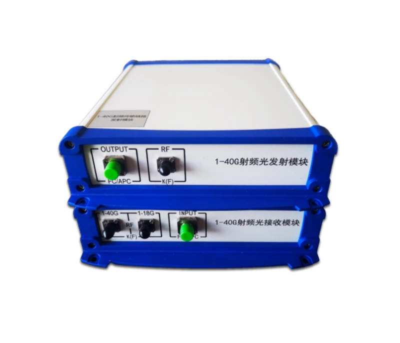
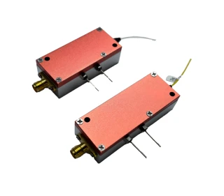
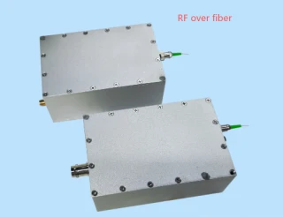
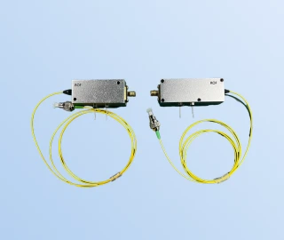
The Rof-ROFBox Series is a high‑performance family of analog broadband external modulation optical transceiver modules engineered for demanding RF‑over‑fiber applications. Designed to transport radio frequency signals over optical fiber in the 1–40 GHz range, these transceivers deliver low‑distortion, high‑linearity links for advanced microwave and millimeter‑wave systems. By converting RF signals to the optical domain and back with an external modulation architecture, the ROFBox series provides a superior alternative to bulky and lossy coaxial cables or waveguides, especially over long distances or in electromagnetically harsh environments.
Operating at 1310 nm and 1550 nm telecom wavelengths, the ROFBox modules are optimized for integration into existing fiber infrastructures used in modern communication networks, satellite ground stations, and radar facilities. The external modulation scheme, combined with high‑quality lasers and optical amplifiers, offers excellent RF response flatness across wide bandwidths, ensuring faithful transport of complex analog and digitally modulated signals. This architecture supports a transparent working mode, making the transceivers protocol‑agnostic and compatible with diverse signal formats, coding schemes, and communication standards without the need for additional conversion or processing.
The Rof‑ROFBox Series is available in several bandwidth configurations to meet different system requirements: 1–18 GHz, 18–40 GHz, and a full 1–40 GHz option. Typical link gain is designed around 0 dB for a 0 dBm RF input, providing a balanced link that simplifies cascaded system design and gain budgeting. In‑band flatness is tightly controlled, with typical variations kept within a few decibels across the specified band, which is essential for applications such as phased‑array beamforming, broadband EW systems, and high‑resolution radar where amplitude uniformity across frequency directly impacts performance. A wide dynamic range and a P‑1 dB input level above 15 dBm ensure that the modules can accommodate both low‑level and relatively strong RF signals while maintaining low intermodulation distortion.
To maximize stability and reliability, the ROFBox modules integrate automatic power control (APC) and automatic temperature control (ATC) circuits. These internal control loops actively regulate the laser output and maintain consistent operating conditions, resulting in improved long‑term gain stability and reduced performance drift with temperature. The built‑in high‑performance laser and optical amplifier stage enable gain regulation and automatic control of optical output, helping to compensate for fiber loss and connector variations in the field. Additionally, a built‑in RF driver amplifier enhances application flexibility, allowing designers to simplify external RF conditioning circuitry and shorten the integration path between the RF front‑end and the fiber link.
Mechanical and optical options are tailored to professional RF and photonic systems. The ROFBox platform supports both single‑mode (SM) and polarization‑maintaining (PM) fiber types, enabling use in standard telecom environments or more specialized coherent and polarization‑sensitive systems. FC/APC fiber connectors are typically used to minimize back‑reflection and improve optical return loss, which is critical for maintaining signal integrity in high‑frequency analog links. RF ports are presented on industry‑standard coaxial connectors such as SMA and 2.92 mm types, ensuring compatibility with a wide variety of RF test equipment, antennas, and system front ends commonly used in broadband microwave and millimeter‑wave applications.
Robust environmental design allows the Rof‑ROFBox Series to operate in a wide ambient temperature range from approximately −40 °C to +70 °C, with storage capabilities extending even further. This makes the modules suitable for deployment in outdoor remote antenna units, mobile platforms, and shelter‑less installations. The devices are engineered to tolerate high relative humidity, supporting reliable operation in challenging climatic conditions. Powering options include internal battery or external adapter, with common supply voltages such as DC 12 V or AC 220 V, offering flexibility for both laboratory use and permanent field installations.
Typical use cases for the ROFBox family include remote antenna remoting in wireless communication systems, where RF‑over‑fiber links decouple antenna placement from electronics shelters to optimize coverage and reduce feeder loss. In timing and reference signal distribution, the modules transport low‑phase‑noise references over long distances with minimal added jitter, making them suitable for synchronization of distributed radar nodes, satellite ground stations, and test ranges.
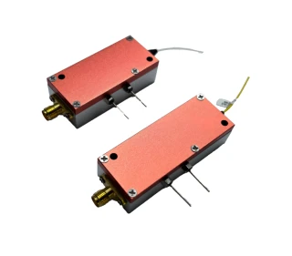
RofBox Analog Broadband External Modulation Optical Transceiver Module 1-40GHz
Specifications
| Signaling Rate Per Lane (Transmitter): | Not Specified |
|---|---|
| Signaling Rate Per Lane (Receiver): | Not Specified |
| Lane Center Wavelength: | 1550 nm |
| Operating Wavelength: | 1310/1550 nm (ROFBox-0118), 1550 nm (ROFBox-1840, ROFBox-0140) |
| Operating Frequency Range (ROFBox-0118): | 1–18 GHz |
| Operating Frequency Range (ROFBox-1840): | 18–40 GHz |
| Operating Frequency Range (ROFBox-0140): | 1–40 GHz |
| Link Gain (typical): | 0 dB @ 0 dBm input |
| In-band Flatness (ROFBox-0118): | < ±2 dB @ 0 dBm input |
| In-band Flatness (ROFBox-1840): | < ±3 dB @ 0 dBm input |
| In-band Flatness (ROFBox-0140): | < ±6 dB @ 0 dBm input |
| Electrical Reflection (S11/S22): | < -9 dB |
| Standing Wave Ratio: | < 2 (typical 1.5) |
| P-1dB Input: | > 15 dBm |
| Fiber Type: | Singlemode (SM) or Polarization maintaining (PM) |
| Optical Fiber Connector: | FC/APC |
| RF Interface (ROFBox-0118): | SMA-K |
| RF Interface (ROFBox-1840, ROFBox-0140): | 2.92-K |
| Input/output Impedance: | 50 Ω (full bandwidth) |
| Operating Ambient Temperature: | -40℃ to +70℃ |
| Storage Ambient Temperature: | -55℃ to +85℃ |
| Power Supply: | Built-in battery or adapter power supply |
| Supply Voltage: | DC 12 V or AC 220 V |
| Maximum Input RF Power: | 20 dBm |
| Operating Relative Humidity: | 5% to 95% |
Got questions about specs? Use the inquiry form to ask.
 Download Data Sheet

Features
- Wideband RF-over-Fiber Transmission (1–40 GHz)
Supports ultra‑broadband analog RF signal transport over fiber with models covering 1–18 GHz, 18–40 GHz, and the full 1–40 GHz band, ideal for advanced microwave, radar, 5G, and SATCOM links. - External Modulation Architecture for Superior Linearity
Uses an external modulation scheme instead of direct modulation, significantly improving linearity, noise performance, and spurious‑free dynamic range for demanding analog applications. - Excellent RF Response Flatness
Delivers low in‑band amplitude ripple with typical RF flatness of < ±2 dB (1–18 GHz), < ±3 dB (18–40 GHz), and < ±6 dB (1–40 GHz), ensuring high‑fidelity transmission across the entire operating band. - Transparent Transmission for Any Modulation or Protocol
Operates in a transparent working mode, compatible with a wide range of signal formats, coding schemes, communication standards, and network protocols without requiring protocol conversion. - Dual Telecom Wavelength Operation (1310 nm / 1550 nm)
Supports operation at 1310 nm and 1550 nm (model‑dependent), enabling low‑loss transmission over standard telecom single‑mode fiber and compatibility with existing optical infrastructures. - Integrated APC and ATC for Stable Optical Performance
Built‑in Automatic Power Control (APC) and Automatic Temperature Control (ATC) circuits stabilize laser output over temperature and time, improving long‑term reliability and link consistency. - High‑Performance Laser and Optical Amplifier with Automatic Gain Control
Incorporates a high‑performance laser and optical amplifier module to provide precise gain regulation and automatic control, supporting long fiber runs while maintaining optimal signal levels. - Built‑In RF Driver Amplifier
Equipped with an integrated RF drive amplifier, simplifying system design and offering additional application flexibility by reducing the need for external RF amplification stages. - High Dynamic Range and P1dB Performance
Designed for wide dynamic range analog links, supporting input RF power up to +20 dBm (limit condition) and a typical P‑1 dB input > 15 dBm, suitable for high‑power and multi‑tone applications. - 50 Ω Impedance and Standard RF Interfaces
RF I/O is matched to 50 Ω across the full bandwidth with typical electrical return loss better than –9 dB (S11/S22). Uses standard SMA‑K and 2.92 mm (K‑type) connectors for straightforward RF integration. - Low VSWR for Improved Link Efficiency
Typical RF standing wave ratio of about 1.5 (< 2 specified), reducing reflection losses and ensuring efficient power transfer between RF equipment and the optical transceiver. - Single‑Mode or Polarization‑Maintaining Fiber Options
Available with SM (single‑mode) or PM (polarization‑maintaining) fiber to suit general RF‑over‑fiber deployments or polarization‑sensitive microwave photonics applications. - Industry‑Standard Optical Connectors
Uses FC/APC as the standard connector for low back‑reflection; FC/PC and user‑defined connector options are supported for seamless integration with existing fiber networks. - Flexible Packaging: Module, Desktop, or Custom
Offered as a compact module (M), desktop unit (D), or custom (S) configuration, enabling easy deployment in lab setups, field systems, or OEM integrations. - Remote Antenna Extension over Fiber
Ideal for remote antenna applications, replacing long, lossy coaxial cables or waveguides with low‑loss fiber, greatly extending reach while preserving RF signal integrity. - Optimized for Long‑Distance Analog Fiber Links
Designed for long‑distance analog fiber optic communication, enabling high‑quality transmission over many kilometers with significantly reduced attenuation and improved EMI immunity compared to copper.
Applications
- Remote Antenna Remoting and RF-over-Fiber Links – Transport high-frequency RF signals (1–40 GHz) from tower-top, shipboard, airborne, or remote ground antennas to sheltered equipment rooms over low-loss fiber instead of long coaxial runs. Ideal for satellite earth stations, teleport facilities, maritime communication masts, and remote base stations.
- Long-Distance Analog Fiber Optic Communication – Extend broadband RF and microwave signals over tens of kilometers with minimal degradation using analog optical links. Suitable for centralizing RF processing in broadcast headends, cable distribution hubs, and distributed communication shelters.
- 5G, LTE, and Wireless Fronthaul / C-RAN – Use RF-over-fiber to implement centralized radio access networks, carrying broadband RF from remote radio heads (RRH) to baseband units (BBU). Supports transparent transport of multiple carriers and standards over 1–40 GHz bands, similar to commercial RFoF and C-RAN links used in modern cellular networks.
- Military Tri-Service (Three-Wave) Communication – Support integrated communication for land, sea, and air platforms by replacing heavy, lossy coax with fiber links. Suitable for shipboard communication systems, mobile command posts, tactical communication shelters, and multi-band radio relay sites where high reliability and low RF loss are critical.
- Tracking, Telemetry & Control (TT&C) – Provide high-linearity links for S-band, X-band, Ku-band, and Ka-band TT&C signals between tracking antennas and control centers. Used in satellite ground stations, missile test ranges, aerospace telemetry facilities, and spacecraft monitoring sites that require broadband, low-distortion RF transport.
- Delay Line Systems and RF Timing Adjustment – Implement long, stable RF delay lines using fiber length instead of bulky coaxial cable. Applicable to radar pulse shaping, signal alignment, testing of communication systems, and phase-adjustment networks where precise and repeatable time delays are needed.
- Phased Array Antenna Distribution – Distribute coherent RF signals to large phased array elements over fiber while maintaining phase stability. Suitable for AESA radar systems, EW/ELINT arrays, radio astronomy arrays, and multi-antenna MIMO testbeds that require low phase noise and wide bandwidth.
- Radar and Electronic Warfare (EW) Systems – Transport wideband radar IF/RF signals and EW spectra from remote antennas to protected processing units. Ideal for ground-based radar sites, coastal surveillance radars, airborne radar pods, and electronic support / electronic attack systems requiring wide dynamic range and flat RF response.
- Precision Time and Frequency Distribution – Distribute low-phase-noise reference clocks and timing signals over 1310/1550 nm fiber to remote locations with high stability. Applicable to GNSS timing backup, telecom synchronization, radar timing networks, metrology labs, and distributed oscillator systems.
- Broadband Microwave Test and Measurement Links – Extend RF signals between instruments (spectrum analyzers, vector network analyzers, signal generators, oscilloscopes) and remote test points through analog fiber links. Useful in anechoic chambers, antenna ranges, EMC test sites, and high-voltage or hazardous environments where long coax runs are impractical.
- Satellite Ground Segment IF/RF Transport – Carry L-band, S-band, C-band, X-band, and Ka-band IF or RF from large satellite dishes to indoor equipment racks. Comparable to commercial SATCOM RFoF systems used in teleports, broadcast uplink stations, VSAT hubs, and gateway earth stations.
- Broadcast, CATV, and Headend Signal Distribution – Distribute multi-channel analog and digital RF signals from a central headend to remote hubs over singlemode fiber, minimizing distortion and maintaining flat gain over wide bandwidths. Suitable for TV broadcast facilities, cable TV systems, and large campus AV networks.
- Distributed Antenna Systems (DAS) and In-Building Coverage – Use RF-over-fiber backbones to feed multiple remote antenna units inside large buildings, tunnels, campuses, stadiums, and transportation hubs. Supports transparent transport of multi-standard RF signals, including public safety, cellular, and private radio networks.
- Aerospace and Avionics RF Distribution – Replace heavy coax in aircraft and UAV platforms with lightweight fiber for routing RF between antennas, sensors, and mission computers. Beneficial for airborne radar, ISR payloads, SATCOM terminals, and flight test instrumentation where weight and space are constrained.
Frequently Asked Questions
What is the ROFBox analog broadband external modulation optical transceiver module?
Which ROFBox model should I choose for my frequency range and application?
What are the key RF and optical performance specifications of the ROFBox Series?
How does the ROFBox module work and what is the benefit of external modulation?
What power supply and environmental conditions are required for the ROFBox Series?
What interfaces and connectors are provided on ROFBox optical transceiver modules?
What are the main applications of the ROFBox analog broadband radio‑over‑fiber link?
Got more questions? Use the inquiry form to ask the supplier directly.
Similar Products


Your inquiry has been received.
Create an account by adding a password
Why create an account?
- Auto-complete inquiry forms
- View and manage all your past messages
- Save products to your favorites
- Close your account anytime — no hassle