
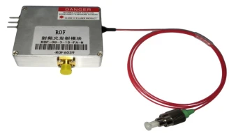
Description
1–10 GHz Radio-over-Fiber (RoF) Module for High-Fidelity RF over Optical Links
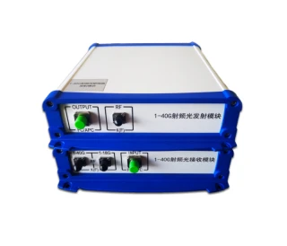
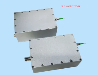
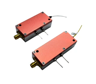
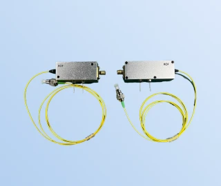
The 1–10 GHz RoF Module from Beijing Rofea Optoelectronics Co., Ltd. is a broadband radio‑over‑fiber transmitter/receiver solution designed for transparent transport of RF signals over optical fiber. Operating from 1 GHz up to 10 GHz, it enables low‑distortion distribution of microwave and RF signals in applications such as long‑distance analog optical communication, microwave delay lines, TT&C systems, and general RF signal remoting. In contrast to many narrowband or digitally constrained links, this analog RoF module passes signal formats transparently, preserving waveform integrity and timing without imposing protocol or modulation restrictions.
Engineered for large dynamic range, the module supports input RF powers from −70 dBm to +15 dBm with a typical spurious‑free dynamic range (SFDR) of 103 dB/Hz2/3 at 1 GHz. This makes it suitable for demanding microwave links where weak signals must coexist with stronger carriers without significant intermodulation products. A 1 dB compression point up to 20 dBm enables the system to handle higher‑level inputs while maintaining linearity. With in‑band RF flatness of approximately ±1.8 dB across the 1–10 GHz range, the module preserves the amplitude profile of wideband signals, which is critical for multi‑carrier, spread‑spectrum, or complex modulated waveforms.
The optical front end supports operation at 1310 nm and 1550 nm, as well as DWDM and CWDM wavelengths, allowing integration into existing fiber‑optic infrastructures and wavelength‑division multiplexed networks. A typical output optical power of 10 mW and an SMSR of 35–45 dB contribute to clean spectral performance, while ≥30 dB optical isolation helps suppress back‑reflections and crosstalk. The receiver photodiode offers a typical responsivity of 0.9 A/W (0.85 A/W minimum) over an operating wavelength range of 1100–1700 nm, supporting efficient optical‑to‑electrical conversion for a variety of fiber plant conditions and link budgets.
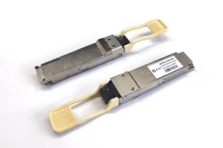
Designed with practical deployment in mind, the 1–10 GHz RoF module combines performance with compactness and low power consumption. It operates from a single 5 V DC supply, with power consumption up to 10 W, making it suitable for integration into space‑constrained racks, outdoor enclosures, or airborne and mobile platforms where power efficiency is important. The compact 95 mm × 60 mm × 21 mm form factor simplifies mounting in existing RF or optical chassis, including test setups and production environments where multiple links may be deployed in parallel.
With its combination of wide operating bandwidth, excellent RF flatness, large dynamic range, and support for standard telecom wavelengths, this RoF module provides a robust platform for extending high‑frequency RF signals over long fiber distances. It is well suited for upgrading legacy coaxial runs to fiber, implementing low‑loss microwave distribution networks in laboratories or antenna farms, and supporting time‑critical RF links in radar, telemetry, and communication systems that demand high linearity and stable performance.
1–10GHz Radio over Fiber Module Analog Optical RF Transmission
Specifications
| Signaling Rate Per Lane (Transmitter): | Not Specified |
|---|---|
| Signaling Rate Per Lane (Receiver): | Not Specified |
| Lane Center Wavelength: | 1550 nm |
| Operating Frequency: | 1–10 GHz |
| Input RF Power: | -70 to +15 dBm |
| RF Gain: | -30 dB |
| In-band Flatness: | ±1.8 dB |
| 1 DB Compression Point: | 20 dBm |
| SFDR@1GHz: | 103 dB/Hz^(2/3) |
| IMD3: | 30 dBc |
| Operating Wavelength (system): | 1310 nm / 1550 nm / DWDM / CWDM |
| RIN: | -145 dB/Hz |
| SMSR: | 35–45 dB |
| Optical Isolation: | 30 dB |
| Transmitter Output Power: | 10 mW |
| Transmitter Operating Wavelength Range: | 1100–1700 nm |
| Receiver Response: | 0.85–0.9 A/W |
| Power Supply: | DC 5 V |
| Power Consumption: | ≤10 W |
| Dimension: | 95×60×21 mm |
Got questions about specs? Use the inquiry form to ask.
 Download Data Sheet

Features
- Wideband 1–10 GHz Operation – Supports RF signal transmission and distribution across a broad 1–10 GHz frequency range, ideal for modern broadband and microwave systems.
- Large Dynamic Range – Handles ultra‑low to relatively high RF input levels from −70 dBm to +15 dBm, enabling high‑fidelity transmission of weak and strong signals in a single link.
- Excellent Linearity & High SFDR – Spurious‑Free Dynamic Range (SFDR) of 103 dB/Hz2/3 @ 1 GHz and 1 dB compression point up to 20 dBm ensure low distortion for demanding analog and digital modulation formats.
- Good In‑Band Flatness – In‑band RF response flatness within −1.8 dB to +1.8 dB minimizes amplitude variation across 1–10 GHz, improving system accuracy and link budget predictability.
- Signal‑Format Transparent RoF Link – No signal format restriction; supports analog, digital, and complex modulation schemes (QAM, OFDM, multi‑tone, etc.) with transparent, protocol‑agnostic transmission.
- Low Noise Performance – Low Relative Intensity Noise (RIN) down to −145 dB/Hz and high SMSR of 35–45 dB reduce phase noise and crosstalk, preserving signal integrity over long fiber distances.
- Multiple Operating Wavelength Options – Supports 1310 nm, 1550 nm, DWDM, and CWDM operation, simplifying integration into existing telecom, CATV, and RF‑over‑fiber infrastructure.
- High Optical Isolation – ≥ 30 dB optical isolation enhances stability, protects internal components, and helps suppress back‑reflections in complex optical networks.
- High‑Power Optical Transmitter – Optical output power up to 10 mW delivers strong link performance and extends the achievable transmission distance without external optical amplification.
- High‑Responsivity Receiver – Photodetector responsivity of 0.85–0.9 A/W supports efficient optical‑to‑RF conversion, improving sensitivity and reducing required optical power at the receiver end.
- Low Power Consumption – Operates from a single DC 5 V supply with maximum power consumption ≤ 10 W, enabling energy‑efficient deployment in dense systems and remote locations.
- Compact Module Design – Small footprint of 95 × 60 × 21 mm saves rack and enclosure space, making it suitable for base stations, shelters, test setups, and airborne or mobile platforms.
- Robust and Reliable Construction – Industrial‑grade design ensures stable RF and optical performance in long‑term operation for telecom, satellite ground stations, and defense applications.
- Ideal for Long‑Distance Analog Optical Links – Optimized for low‑distortion analog RF‑over‑fiber transmission in point‑to‑point and point‑to‑multipoint architectures.
- Microwave Delay Line & Phase Distribution – Suitable for creating low‑loss microwave delay lines and precise phase distribution networks used in phased‑array radar, EW systems, and timing applications.
- Telemetry, Tracking & Command (TT&C) – Meets typical RF and linearity requirements for satellite and aerospace TT&C ground segment links where signal integrity is critical.
- RF Signal Transport & Remoting – Enables remote placement of antennas and RF front‑ends by transporting RF over fiber, reducing coaxial cable loss and susceptibility to EMI.
- Compatible with DWDM/CWDM Networks – Wavelength compatibility allows dense integration of multiple RF channels over a single fiber, maximizing.
Applications
The 1–10 GHz Radio-over-Fiber (RoF) Module from Beijing Rofea Optoelectronics Co., Ltd. is designed for high‑performance analog optical links in the L‑, S‑, C‑ and X‑band frequency ranges. With wideband operation, low noise, large dynamic range, and excellent RF flatness, it supports demanding RF and microwave systems in both commercial and defense environments.
- Long‑Distance Analog RF over Fiber Links
Ideal for transporting broadband RF signals over kilometers of single‑mode fiber while preserving signal integrity. Common in distributed antenna systems (DAS), remote radio head (RRH) deployments, and centralized RF processing architectures. - Remote Antenna and Distributed Antenna Systems (DAS)
Used to extend RF coverage in large campuses, tunnels, stadiums, mines, and buildings by locating antennas remotely and feeding them via low‑loss optical fiber links instead of long coaxial cables. - Microwave Delay Lines and Delay‑Based Signal Processing
Provides stable, low‑loss time delay for RF and microwave signals. Suitable for radar delay lines, beamforming networks, pulse compression systems, phase‑array calibration, and time‑alignment of multi‑channel systems. - Telemetry, Tracking and Command (TT&C)
Supports transparent transmission of wideband telemetry channels between remote RF front ends (antennas, feeds, tracking stations) and centralized baseband/IF processing equipment. Useful in satellite TT&C ground stations, missile test ranges, and aerospace measurement platforms. - Radio Frequency Signal Transport and Remote IF Distribution
Point‑to‑point or point‑to‑multipoint RF distribution between shelters, control rooms, and antenna sites. Replaces bulky coax runs with optical fiber links, minimizing RF loss and improving system reliability at 1–10 GHz. - Radar and Electronic Warfare (EW) RF Links
Suitable for transporting radar intermediate frequency (IF) or RF signals to remote processing units. Used in phased‑array radar, multi‑static radar, and EW test ranges where low distortion, low noise, and high spurious‑free dynamic range (SFDR) are critical. - 5G, LTE, and Wireless Infrastructure Fronthaul
Enables analog RF fronthaul for 4G/5G macro cells, small cells, and test beds. The module’s frequency range and SFDR support wideband modulation formats used in modern cellular, Wi‑Fi backhaul, and point‑to‑point microwave links. - Satellite Ground Station RF over Fiber Links
Transport of L‑band, S‑band, and C‑band signals between satellite dishes and indoor equipment rooms. Helps reduce feeder loss, simplifies siting of antennas, and improves maintainability of gateway and earth station systems. - Broadcast and Contribution Links
Suitable for studio‑to‑transmitter links (STL), remote broadcast pickup, and RF distribution in broadcast facilities where low distortion analog fiber transport of IF/RF is required. - Laboratory, Production Test, and Measurement Systems
Used in RF/microwave test setups to route signals between shielded rooms, anechoic chambers, and control labs. Reduces cable‑related loss and phase drift, improving repeatability in automated test systems. - Timing, Reference, and Local Oscillator (LO) Distribution
Distribution of low‑phase‑noise RF reference and LO signals over fiber to multiple remote subsystems. Beneficial in large phased‑array systems, synchronization networks, and coherent measurement setups. - Cable Replacement and Infrastructure Simplification
Replacement of long, heavy, and lossy coaxial cables with lightweight fiber, especially where cable trays are crowded or where long outdoor runs are required. Reduces installation cost and improves long‑term stability. - Military Ranges, Secure Facilities, and Shipboard RF Networks
Use in secure or harsh environments to route sensitive RF signals over fiber, gaining immunity to electromagnetic interference (EMI), lightning, and crosstalk common in metallic cabling. - Microwave Radio Links and Backhaul Extension
Integration with microwave radios and point‑to‑point links to extend reach beyond traditional RF cable limits, or to position antennas at optimal locations while keeping active electronics in protected areas. - Research, Education, and Demonstration Systems
Suitable for university labs and research institutes working on microwave photonics, RoF systems, advanced modulation formats, and high‑frequency communication experiments covering the 1–10 GHz band.
Frequently Asked Questions
What is the 1–10 GHz RoF (Radio over Fiber) module and what does it do?
What are the key technical specifications of this 1–10 GHz RF over fiber module?
What are typical applications of this 1–10 GHz RoF link?
How does this RF over fiber module compare to similar RoF links on the market?
Is the 1–10 GHz RoF module protocol‑independent and what signals can it transmit?
What fiber and wavelength options can be used with this RF over fiber module?
How do I power, integrate, and protect the 1–10 GHz RoF module in my system?
Got more questions? Use the inquiry form to ask the supplier directly.
Similar Products
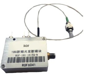
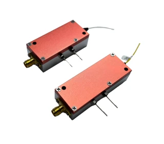


Your inquiry has been received.
Create an account by adding a password
Why create an account?
- Auto-complete inquiry forms
- View and manage all your past messages
- Save products to your favorites
- Close your account anytime — no hassle