
Description
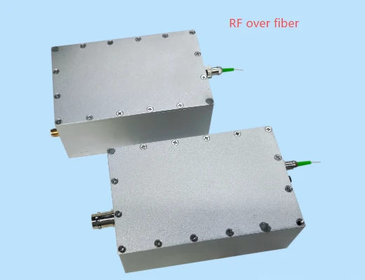
The R-ROFxxxxT Series RF over Fiber (RFoF) Analog Broadband Optical Transceiver Link is an advanced photoelectric transmission solution engineered for accurate, real-time transport of DC to 500 MHz or DC to 1 GHz electrical signals over single‑mode optical fiber. Designed to perform reliably in complex and harsh electromagnetic environments, this system decouples sensitive measurements from noisy test areas, making it ideal for high‑precision field testing, laboratory use, and distributed RF transport in applications where traditional coaxial cabling is impractical or susceptible to interference.
Unlike conventional RF links that degrade in high electromagnetic field strength regions, the R-ROFxxxxT uses optical transmission with automatic level control and adaptive optical insertion loss compensation. The transmitting module accepts signals through a versatile 1 MΩ/50 Ω BNC input, allowing direct connection to current probes, high‑voltage probes, antennas, or other RF and voltage sensing devices. The input electrical signal is linearly modulated onto an optical carrier and sent through a single‑mode fiber to the receiving module, which precisely reconstructs the original RF waveform. This architecture provides an instantaneous dynamic range greater than 55 dB and maintains stable performance across distances of 1 km or more without being affected by external electromagnetic noise.
To match the requirements of demanding RF measurement tasks, the R-ROFxxxxT Series incorporates multiple attenuation and gain control mechanisms. An integrated adaptive adjustable attenuator (1:1 / 10:1 / 100:1) enables optimization of input and output levels for different signal amplitudes, extending the usable dynamic range from low‑level analog signals up to high‑voltage inputs. The input impedance of 1 MΩ or 50 Ω can be software‑selected via an upper‑computer interface, supporting both high‑impedance and standard RF measurement scenarios. On the receive side, a 50 Ω BNC output and flat in‑band frequency response (±1 dB to 500 MHz and ±1.5 dB to 1 GHz) help ensure that the transmitted signal retains its amplitude and spectral characteristics for accurate analysis with oscilloscopes, spectrum analyzers, digitizers, or other test equipment.
The system’s resilience in strong electromagnetic fields sets it apart from conventional RF transport methods. With a maximum anti‑field‑strength capability greater than 500 kV/m, the R-ROFxxxxT Series is well suited for environments such as high‑voltage substations, power electronics test labs, EMC/EMI test chambers, radar installations, and pulsed‑power facilities where metal cabling could pick up large induced currents or be directly damaged. By moving measurement and control electronics to a safe, low‑field location and using optical fiber as the transmission medium, the device minimizes signal distortion, improves operator safety, and enhances long‑term system reliability.
The RFoF link is also optimized for mobile and remote deployments. Both the transmitter and receiver modules support battery operation, and the transmitter integrates a built‑in rechargeable power source providing up to 48 hours of continuous full‑power use. A low‑power standby mode can be engaged remotely when the system is idle, significantly extending operational time in the field. LED indicators provide clear visual status of power, link, and operating conditions, enabling quick diagnostics during setup and use. For calibration checks and functional verification, the transmitter includes an internal 500 Hz square‑wave test signal (0–0.5 V), which can be used to confirm chain integrity and response without external signal generators.
In terms of physical design, the R-ROFxxxxT Series balances ruggedness with portability. Compact module dimensions of approximately 100 mm × 65 mm × 40 mm and a weight of about 450 g facilitate easy installation near sensors or inside confined test fixtures. The optical interface uses industry‑standard FC/APC connectors at wavelengths of 1310 nm (transmitter) and 1550 nm (receiver), providing low‑loss single‑mode connectivity compatible with commonly available test and telecom‑grade fibers. These attributes make integration straightforward in both temporary test setups and permanent RF distribution infrastructures, such as shipboard RF networks or satellite ground station timing and reference signal distribution.
With its combination of wide bandwidth, high dynamic range, field‑programmable attenuation and impedance, automatic optical loss compensation, and robust construction, the R-ROFxxxxT Series RF over Fiber Analog Broadband Optical Transceiver Link offers a reliable alternative to coax‑based RF transport.
Rof Analog Broadband Optical Transceiver Link RF Over Fiber
Specifications
| Lane Center Wavelength: | 1310 nm |
|---|---|
| Product Type: | RF over fiber Link analog broadband optical transceiver link |
| Series: | R-ROFxxxxT |
| Bandwidth Options: | DC–500 MHz, DC–1 GHz |
| In-band Flatness (DC–500 MHz): | ±1 dB |
| In-band Flatness (DC–1 GHz): | ±1.5 dB |
| Link Attenuation Levels: | 1:1 / 10:1 / 100:1 |
| Input Impedance (link): | 1 MΩ / 50 Ω, selectable |
| Output Impedance (link): | 50 Ω |
| Maximum Output Amplitude: | ±0.7 Vp |
| Instantaneous Dynamic Range: | >55 dB |
| Output Noise: | 2 mV RMS, 50 Ω |
| Optical Insertion Loss Compensation: | Automatic |
| Laser Wavelength (TX/RX): | 1310 nm / 1550 nm |
| Maximum Anti-field Strength Capability: | >500 kV/m |
| Operating Temperature: | -10 ℃ to +50 ℃ |
| Maximum Transmission Distance: | ≥1 km |
| TX Input Attenuation Ratio: | 1:1 / 10:1 / 100:1 |
| TX Input Impedance: | 1 MΩ / 50 Ω, selectable |
| TX Maximum Input Power (CW): | 0.4 W (Input = 50 Ω) |
| TX Maximum Input Voltage Amplitude (1:1): | ±3 Vp |
| TX Maximum Input Voltage Amplitude (10:1): | ±30 Vp |
| TX Maximum Input Voltage Amplitude (100:1): | ±125 Vp |
| TX Input Protection Voltage Amplitude (1:1): | ±0.7 Vp |
| TX Input Protection Voltage Amplitude (10:1): | ±7 Vp |
| TX Input Protection Voltage Amplitude (100:1): | ±70 Vp |
| RF Input Interface (TX): | BNC female |
| Laser Output Power (TX): | <5 mW |
| Built-in Test Signal: | Square wave, 500 Hz, 0–0.5 V |
| Optical Interface: | FC/APC |
| Power Supply Method (TX): | Built-in battery |
| Full-power Working Hours: | 48 h |
| Overall Dimensions (TX): | 100 mm × 65 mm × 40 mm |
| Weight (TX): | 450 g |
| RF Output Port (RX): | BNC female, 50 Ω |
Got questions about specs? Use the inquiry form to ask.
 Download Data Sheet

Features
- Wideband RF Over Fiber Transmission (DC to 500 MHz / 1 GHz)
Supports two optional bandwidth configurations (DC–500 MHz or DC–1 GHz), enabling precise real-time transmission of low-frequency to high-frequency analog RF signals over optical fiber for laboratory, industrial, and field applications. - High-Fidelity Analog Signal Link with Excellent Flatness
Ensures accurate signal integrity with in-band flatness of ±1 dB (DC–500 MHz) and ±1.5 dB (DC–1 GHz), making it suitable for precision measurement, test and measurement systems, and broadband RF monitoring. - Long-Distance, Low-Loss Optical Transmission
Converts RF signals to optical and back to RF using single-mode fiber for transmission distances of ≥1 km, overcoming coaxial cable loss, phase distortion, and electromagnetic interference in harsh environments. - Automatic Optical Insertion Loss Compensation
Integrated automatic level control (ALC) maintains a stable optical signal regardless of fiber loss variations, temperature changes, or connector aging, ensuring consistent gain and repeatable measurement accuracy. - Adjustable Gain & Optimized Dynamic Range
Built-in adaptive attenuator with selectable attenuation levels (1:1 / 10:1 / 100:1) and input/gain control via upper computer enhances the instantaneous dynamic range (>55 dB), enabling accurate measurements from small-signal to high-level RF inputs. - Wide Input Impedance and Flexible Connectivity
Selectable input impedance of 1 MΩ or 50 Ω (remotely set by software) with BNC female interface allows direct connection to current probes, high-voltage probes, oscilloscopes, sensors, and RF test instruments. - High Input Voltage Handling & Protection
Supports maximum continuous input power of 0.4 W (50 Ω) with input voltage ranges up to ±3 Vp (1:1), ±30 Vp (10:1), and ±125 Vp (100:1), plus dedicated protection thresholds (±0.7 Vp / ±7 Vp / ±70 Vp) to safeguard the transceiver against over-voltage. - Low-Noise Output for Precision Measurement
Receiver features a 50 Ω BNC output with low output noise (~2 mV RMS @ 50 Ω), enabling high signal-to-noise ratio for demanding applications such as EMC testing, radar front-ends, and scientific experiments. - Exceptional EMC and High-Field Immunity
Designed for operation in complex electromagnetic environments with maximum anti-field strength capability >500 kV/m, ideal for electromagnetic field testing, high-voltage labs, pulsed power environments, and military/defense RF sites. - Battery-Powered, Portable Design
Both TX and RX modules support built-in battery operation, with the transmitter offering up to 48 hours of continuous full-power work time, making the system well-suited for field measurements, mobile platforms, and temporary test setups. - Low-Power Standby with Remote Wake-Up
Remote-controlled standby mode reduces power consumption when the link is idle, extending battery life. LED status indicators provide clear visual feedback of operating and standby states. - Remote Control & Software Configuration
Attenuation ratio (1:1 / 10:1 / 100:1), input impedance selection (1 MΩ / 50 Ω), and link parameters are controlled by an upper computer, enabling easy integration into automated test systems and remote monitoring platforms. - Integrated Test Signal Generator
Built-in 500 Hz square-wave test signal (0–0.5 V) facilitates quick link verification, calibration, and troubleshooting without requiring additional external signal sources. - High-Performance Optical Engine (1310 / 1550 nm)
Utilizes 1310 nm laser at the transmitter and 1550 nm wavelength at the receiver side with optical output power <5 mW, providing a robust, telecom-grade optical layer and high reliability in long-term operation. - Standardized Fiber Interface
Equipped with FC/APC single-mode optical interface to minimize back-reflection and ensure stable link performance, fully compatible with standard telecom-grade fiber infrastructure. - Compact, Lightweight Form Factor
Transmitter module dimensions of approximately 100 mm × 65 mm × 40 mm and weight of about 450 g support handheld and portable use, mounting in tight spaces, and easy integration inside test racks or near antennas and sensors. - Reliable Operation Over Wide Temperature Range
Designed for operating temperatures from -10 ℃ to +50 ℃, enabling dependable performance in indoor labs, industrial halls, shielded rooms, vehicles, and semi-outdoor environments.
Applications
Applications of R-ROFxxxxT Series RF over Fiber Analog Broadband Optical Transceiver Link
The R-ROFxxxxT series RF over fiber link is designed for high‑fidelity, real‑time transmission of DC to 500 MHz / 1 GHz analog and RF signals over single‑mode fiber in harsh electromagnetic environments. Powered by batteries, featuring 1 MΩ/50 Ω selectable input and wide dynamic range, it is suitable for a broad range of professional test, measurement, communications, and monitoring applications.
1. Electromagnetic Field Testing and High‑EMI Environments
- Remote measurement of analog and RF signals in strong electromagnetic fields (up to >500 kV/m)
- EMC/EMI compliance testing in anechoic chambers and reverberation chambers
- High‑voltage laboratory measurements (GIS, transformers, switchgear, busbars)
- Plasma, pulsed‑power, and particle accelerator diagnostics where copper cables cannot be used
- Isolation and signal transport inside MRI, NMR, and other high‑field medical/industrial equipment
2. Remote Transmission of Analog and RF Test Signals
- Point‑to‑point analog signal extension from sensors and probes over >1 km fiber
- Transmission of oscilloscope probe signals from hazardous or inaccessible areas
- Remote monitoring of high‑voltage probes and current probes in power systems
- Time‑critical RF signal transport from test fixtures to measurement instruments
- Low‑noise extension of sensitive analog measurement channels in noisy industrial plants
3. RF Over Fiber Links for Communications and Distribution
- RF over fiber (RFoF) distribution for L‑band and sub‑GHz signal transport
- Remote antenna extension for base stations, telemetry, and communication links
- Microwave down‑converted IF signal transport from outdoor units to indoor equipment
- RF signal routing between shielded rooms, test cells, and equipment racks
- Analog link for monitoring and re‑broadcast of VHF/UHF communication channels
4. Shipborne RF Distribution and Naval Systems
- Shipborne RF distribution from deck‑mounted antennas to below‑deck processing units
- EMI‑immune RF links between radar, communication, and electronic support systems
- Remote monitoring of RF signals in confined metal structures where coax loss is high
- Signal distribution in naval combat information centers and integrated mast systems
5. Satellite Ground Station and Timing Signal Transmission
- Satellite ground station clock transmission and reference distribution over fiber
- Transport of L‑band IF signals from outdoor dishes to indoor receivers
- Distribution of 10 MHz, 1 PPS, and other precision timing signals with low noise
- GNSS/GPS signal extension to underground, shielded, or remote facilities
- Phase‑coherent RF reference links for phased‑array and beamforming systems
6. Power Grid, High‑Voltage, and Substation Monitoring
- Isolation and transmission of measurement signals in HV substations and switchyards
- Online monitoring of partial discharge, surge, and transient events
- Wideband current and voltage waveform acquisition in power quality analysis
- Remote condition monitoring of transformers, reactors, and transmission lines
- Safe measurement in high‑potential environments using fiber isolation
7. Defense, Radar, and Electronic Warfare
- Remote RF sensing for radar and electronic warfare test ranges
- Transport of wideband RF and IF signals from antennas to protected shelters
- Distributed RF measurement points in high‑EMI military platforms
- Real‑time monitoring of telemetry, guidance, and tracking signals
- Low‑loss, low‑distortion RF links for field trials and weapon system testing
8. Industrial, Automotive, and Transportation Testing
- RF and analog signal transmission in automotive EMC test facilities
- On‑vehicle RF measurement links for electric and autonomous vehicle testing
- Analog signal transport in railway, aerospace, and transportation test benches
- Noise‑immune signal links in factories, refineries, and heavy industrial sites
- Condition monitoring of rotating machinery with EMI‑resilient signal paths
9. Scientific Research and Laboratory Instrumentation
- Laboratory‑grade RF over fiber links for physics and engineering research
- Signal acquisition in high‑voltage, high‑field, or radiation environments
- Fiber‑isolated connections between experimental setups and control rooms
- Low‑distortion analog links for spectroscopy,
Frequently Asked Questions
What is the R-ROFxxxxT RF over Fiber analog broadband optical transceiver link and what problem does it solve?
What are the key technical specifications and performance characteristics of the R-ROFxxxxT RF over Fiber link?
How do I connect and use the R-ROFxxxxT RF over Fiber link in my measurement or RF distribution setup?
What input voltage and power levels can the R-ROFxxxxT transmitter handle, and how do the 1:1, 10:1, and 100:1 attenuation settings work?
In what applications is the R-ROFxxxxT RF over Fiber link typically used compared to other RFoF systems?
How does the automatic optical insertion loss compensation and gain control improve RF over fiber performance?
What are the power, size, and environmental specifications and can the R-ROFxxxxT be used in the field?
Got more questions? Use the inquiry form to ask the supplier directly.
Similar Products


Your inquiry has been received.
Create an account by adding a password
Why create an account?
- Auto-complete inquiry forms
- View and manage all your past messages
- Save products to your favorites
- Close your account anytime — no hassle