
Description
Mini 0.05–6 GHz Analog Wideband Transceiver Module High-Performance RF-over-Fiber Transceiver for 0.05–6 GHz Systems
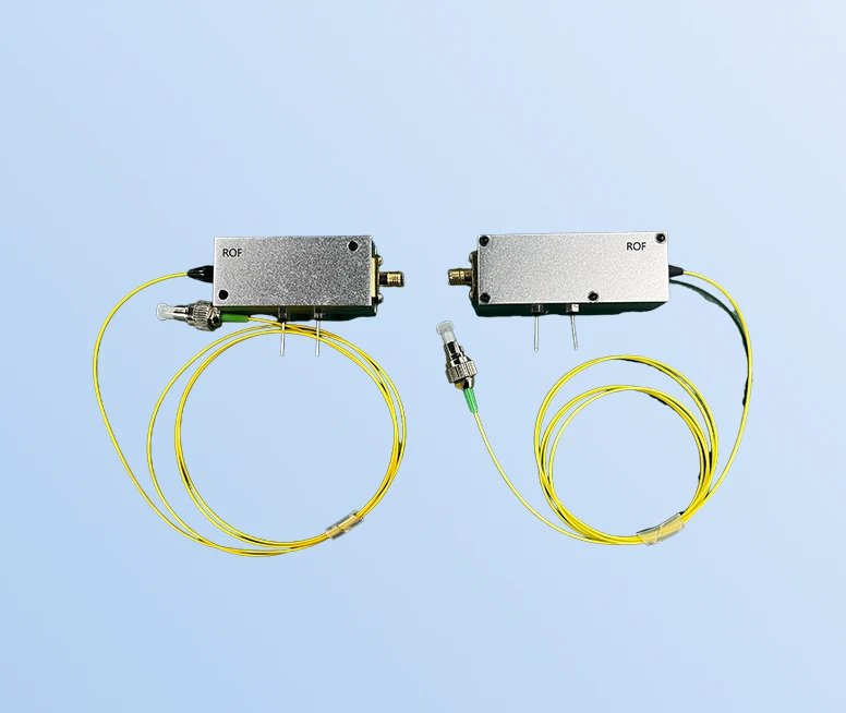
The Mini 0.05–6 GHz Analog Wideband Transceiver Module from Beijing Rofea Optoelectronics Co., Ltd. is a compact, low-cost RF-over-fiber solution engineered for demanding broadband applications. Covering a continuous bandwidth from 50 MHz to 6 GHz, this module enables high-fidelity transmission of analog RF signals over single-mode optical fiber, significantly extending link distances while preserving signal integrity. Designed as a matched transmitter–receiver pair, it provides seamless RF-to-optical and optical-to-RF conversion, ideal for modern wireless, satellite, and radar distribution networks where low loss, low noise, and excellent linearity are essential.
In contrast to traditional coaxial cable links that suffer from attenuation, EMI susceptibility, and distance limitations, this analog wideband transceiver leverages single-mode fiber to deliver stable performance over long runs with minimal degradation. A very high spurious-free dynamic range (SFDR) and flat frequency response across the specified band help maintain signal quality for multi-carrier, high‑order modulation formats used in WiMAX, LTE, and 5G. Its tight cast metal housing and SMA/FC‑APC interfaces make it straightforward to integrate into existing RF infrastructures or compact OEM assemblies where shielding and consistent RF characteristics are critical.
Optimized RF and Optical Design for Linear, Low-Noise Links
The transmitter side of the module incorporates a linear, optically isolated FP/DFB laser source operating at 1310 nm or 1550 nm, coupled into standard 9/125 µm single‑mode fiber. This architecture, commonly used in professional RF-over-fiber products worldwide, is selected for its combination of linearity, low RIN (relative intensity noise), and stable performance over temperature. The design supports a typical RF input power level around −5 dBm, with link gain close to 0 dB (−5 dB to 0 dB range), enabling easy level planning in wider RF systems and minimizing the need for additional amplification stages.
On the receive side, a high-performance InGaAs photodiode converts the optical signal back to RF with wide bandwidth and low distortion. InGaAs detectors are standard for 1.3/1.5 µm fiber systems thanks to their high responsivity, broad frequency response, and low noise, which directly support the module’s high SFDR specification. The combination of 50 MHz low‑frequency cutoff and 6 GHz high‑frequency cutoff allows the unit to handle a broad variety of signals, from sub‑GHz communications and IF bands up to higher microwave carriers, making it suitable for multi‑band or reconfigurable radio platforms.
Broadband Performance and Stable Frequency Response
The Mini analog wideband transceiver module is engineered to deliver a flat response over its operating range, with typical frequency response variation of ±1.5 dB (maximum ±2 dB) from 0.6 GHz to 6 GHz. This level of flatness is comparable to many dedicated RF-over-fiber links used in professional telecom and measurement systems, and it is important for applications that carry multiple channels or wideband modulated signals simultaneously. A controlled standing wave ratio (VSWR around 1.5) and fixed 50 ohm impedance on the SMA RF port promote good matching with standard RF components, reducing reflections and ripple in the passband.
The optical interface uses FC/APC connectors, which are widely preferred in RF-over-fiber and CATV systems because the angled polish significantly reduces back reflection into the laser and photodiode. Lower reflections translate into improved linearity and lower intermodulation distortion, essential for maintaining the advertised high SFDR. By following the same connector and fiber standards seen in similar broadband modules across the industry, this product integrates smoothly into existing optical networks without demanding exotic cabling or custom terminations.
Compact Module Form Factor for OEM Integration
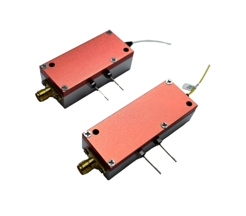
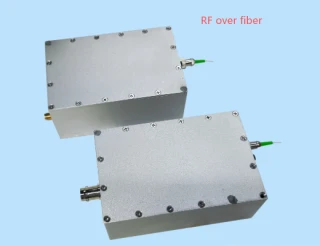
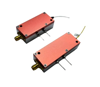
Housed in a tight cast metal case, the Mini 0.05–6 GHz module offers robust electromagnetic shielding and mechanical protection, which is critical in dense RF environments such as base stations, shipborne systems, or test racks. The mechanical design supports convenient mounting in equipment chassis and allows short RF runs from local radios or instrumentation to the SMA interface, with the bulk of the path handled efficiently over fiber. This compact form factor is consistent with many OEM‑focused RF-over-fiber solutions in the market, making it suitable for integration into custom enclosures or subsystems as part of larger communication or sensing platforms.
Mini 0.05 to 6GHz Analog Wideband Fiber Optic Transceiver Module
Specifications
| Signaling Rate Per Lane (Transmitter): | Not Specified |
|---|---|
| Signaling Rate Per Lane (Receiver): | Not Specified |
| Lane Center Wavelength: | 1550 nm |
| Bandwidth Response: | 50 MHz to 6 GHz |
| High Frequency Cut-off (HFC): | 6 GHz |
| Low Frequency Cutoff (LFC): | 50 MHz |
| Frequency Response (0.6–6 GHz): | ±1.5 to ±2 dB |
| Supply Voltage VCC: | 4.5–5 V |
| Supply Current ICC: | 100 mA |
| Laser Output Power: | 2–4 mW |
| Transmitter Operating Wavelength: | 1310/1550 nm |
| Receiver Operating Wavelength: | 1310/1550 nm |
| Input RF Power: | -5 dBm |
| Input/Output Impedance Z: | 50 Ω |
| Standing Wave Ratio (VSWR): | 1.5 |
| RF Link Gain: | -5 to 0 dB |
| RF Port: | SMA |
| Optical Fiber Type: | 9/125 μm single-mode fiber |
| Optical Fiber Protective Casing: | 900 μm |
| Optical Connector: | FC/APC |
| Operating Temperature TO: | -25 to 65 ℃ |
| Storage Temperature TS: | -40 to 85 ℃ |
| DC Supply Voltage VDP: | 4.5–5.5 V |
| Maximum RF Input (Tx): | 10 dBm |
| Maximum Optical Input (Rx): | 4 mW |
| Operating Frequency Range: | 0.05–6 GHz |
| Modulation Bandwidth Option 01: | 10–1200 MHz |
| Modulation Bandwidth Option 02: | 50–3000 MHz |
| Modulation Bandwidth Option 03: | 50–6000 MHz |
| Operating Wavelength Option 13: | 1310 nm |
| Operating Wavelength Option 15: | 1550 nm |
| Encapsulation: | Module (M) |
| Connector Options: | FC/APC (FA), user specified (SP) |
Got questions about specs? Use the inquiry form to ask.
 Download Data Sheet

Features
- 0.05–6 GHz Ultra‑Wideband Operation
Supports RF signals from 50 MHz up to 6 GHz, covering L, S, C bands and key wireless standards for versatile broadband RF-over-fiber links. - High Linearity & High SFDR
Engineered for high spurious‑free dynamic range (SFDR), enabling low‑distortion transmission of complex analog and digital modulation formats used in LTE, 5G, WiMAX, and satellite links. - Flat Frequency Response (50 MHz–6 GHz)
Typical gain flatness of ±1.5 to ±2 dB across the 0.6–6 GHz band helps preserve signal integrity and minimizes equalization requirements in wideband RF distribution systems. - Miniature Metal Module Design
Compact, tight cast metal housing provides excellent shielding against EMI/RFI, improves thermal stability, and simplifies integration into crowded RF front‑ends and OEM platforms. - Integrated Two‑Way RF‑Over‑Fiber Link Capability
A matched pair of modules enables full RF-to-optical and optical-to-RF conversion for bidirectional fiber links—ideal for remote radio heads, distributed antenna systems, and RF extension. - InGaAs Photodiode Receiver
High‑performance InGaAs photodiode delivers low noise, high sensitivity, and stable responsivity at 1310/1550 nm, enhancing link budget and dynamic range for long or lossy fiber runs. - Linear FP/DFB Laser Transmitter
Uses isolated FP/DFB laser sources at 1.3 µm and/or 1.5 µm, optimized for analog linearity and low RIN, supporting high‑fidelity transmission for dense carrier and multi‑tone applications. - Single‑Mode Fiber Optimized
Designed for 9/125 µm single‑mode fiber with 900 µm protective coating, allowing low‑loss, long‑distance RF transport with excellent phase and amplitude stability. - Low VSWR, 50 Ω RF Interfaces
50 Ω SMA connectors with typical VSWR of 1.5 help minimize reflections, insertion loss, and mismatch errors in precision RF measurement and communication systems. - Configurable RF Link Gain
RF link gain from –5 dB to 0 dB (typical) for straightforward level planning and easy matching with existing RF chains, amplifiers, and attenuators. - Standard FC/APC Optical Connector
FC/APC interface ensures low back reflection and high stability, critical for analog optical links where reflections can degrade SFDR and increase noise. - Low Power Consumption, Single 5 V Supply
Operates from a single 4.5–5.5 V DC supply with typical current around 100 mA, simplifying power design and enabling deployment in space‑constrained or remote locations. - Robust Environmental Performance
Operating temperature from –25 °C to +65 °C and storage from –40 °C to +85 °C for reliable performance in indoor, outdoor, and shipborne environments. - Multiple Bandwidth Options via Ordering Code
Available modulation bandwidth variants (e.g., 10–1200 MHz, 50–3000 MHz, 50–6000 MHz) to match specific system requirements and optimize cost and performance. - Ideal for Modern Wireless & Defense Applications
Suited for WiMAX, 4G LTE, 5G communication, shipborne RF distribution, satellite earth stations, radar IF transport, and test & measurement RF extension over fiber. - Easy OEM Integration
Module‑style encapsulation with clear pinout and standardized connectors enables quick integration into radios, repeaters, DAS, and lab setups without extensive RF/optical design effort.
Applications
- 5G and 4G LTE Remote Radio Head (RRH) Fronthaul – Transporting RF signals over fiber between baseband units and remote radio heads in distributed and centralized RAN (C‑RAN) architectures for 0.05–6 GHz bands.
- RF over Fiber (RFoF) for Wireless Infrastructure – Extending cellular, PCS, and microwave coverage inside buildings, tunnels, stadiums, campuses, and remote sites via analog RF‑over‑fiber links.
- WiMAX and Broadband Wireless Access Links – Low‑loss, low‑distortion RF transport for WiMAX and other broadband wireless access systems operating up to 6 GHz.
- Distributed Antenna Systems (DAS) – Centralizing RF equipment and distributing multi‑band cellular and public safety signals over fiber to remote antenna units.
- Satellite Earth Station IF and L‑Band Transport – Carrying L‑band and IF signals between antennas, shelters, and control rooms with minimal loss and high spurious‑free dynamic range.
- Shipborne RF Distribution and Maritime Communications – Transmitting radar, navigation, and communication RF signals over fiber to reduce cable weight and EMI on ships and offshore platforms.
- Microwave and mmWave Backhaul IF Transport – Fiber extension of IF or lower‑frequency stages in microwave/mmWave point‑to‑point backhaul links to remote antenna sites.
- Remote Antenna and Tower‐Top Radio Deployment – Locating sensitive RF equipment in controlled environments while placing compact antenna heads at towers or masts.
- Broadcast and Studio–Transmitter Links (STL/TSL) – High‑fidelity RF over fiber transmission between studios, head‑ends, and remote transmitter sites for TV and radio broadcasting.
- CATV, DOCSIS, and Broadband RF Distribution – Transporting wideband RF, cable TV, and broadband signals over single‑mode fiber in campus, MDU, and head‑end distribution networks.
- Test, Measurement, and RF Monitoring Systems – Extending RF test points over fiber from antennas or chambers to lab instruments such as spectrum analyzers and signal analyzers.
- Anechoic Chamber and EMC/EMI Testing – Isolated RF transport into shielded or high‑field environments without long coax runs that degrade wideband signals.
- Radar Signal Transport and Processing – Moving radar RF or IF signals from antenna front‑ends to sheltered processing units over fiber with flat frequency response and high linearity.
- Defense and Electronic Warfare (EW) Systems – Low‑distortion RF over fiber links in EW, SIGINT, and ELINT systems requiring wide bandwidth and high dynamic range.
- GNSS/GPS and Timing Signal Distribution – Remote distribution of L‑band GNSS/GPS and precision timing references over optical fiber to multiple locations.
- Remote Spectrum Monitoring and Interference Detection – Deploying remote RF sensors connected via fiber for continuous monitoring of spectrum usage and interference across large areas.
- Wireless Coverage in Tunnels, Mines, and Underground Facilities – Using RF‑over‑fiber links to feed leaky feeder cables and antennas for mission‑critical communications.
- In‑Building Cellular and Public Safety Coverage – Fiber‑fed RF links for multi‑band cellular, LTE, and public safety radio enhancement systems in complexes and high‑rise buildings.
- Laboratory and R&D Prototyping of RF over Fiber – Rapid development and evaluation of analog RFoF links, linearized transmitters, and wideband photonic front‑ends.
- Remote LO, Reference, and Clock Distribution – Distribution of local oscillator and reference frequency signals over fiber to synchronize remote RF front‑ends and test setups.
- Telemetry, Tracking, and Command (TT&C) – Wideband RF over fiber transport for ground station telemetry and command links supporting satellites and airborne platforms.
- Industrial and Utility RF Communications – Long‑distance, low‑loss RF extension over fiber for SCADA radios, utility networks, and private wireless systems in harsh environments.
- Security, Surveillance, and Sensor Networks – Carrying RF from remote sensors, surveillance receivers, and wireless camera systems over fiber back to central monitoring points.
- Education and Training Laboratories – University and technical labs using wideband transceiver modules for teaching optical communications, RF photonics, and system integration.
Frequently Asked Questions
What is the Mini 0.05–6GHz Analog Wideband Transceiver Module and what does it do?
What are the key specifications and performance characteristics of this RF over fiber transceiver?
How do I select the correct model (wavelength and bandwidth) and interpret the ROF-MINI ordering code?
What are the typical applications of this 0.05–6 GHz RF over fiber transceiver module?
How do I power, connect and integrate the Mini analog wideband transceiver into my RF system?
What are the operating limits, reliability considerations and how do I protect the module?
How does this module compare to other 6 GHz RF over fiber links in terms of SFDR and frequency response?
Got more questions? Use the inquiry form to ask the supplier directly.
Similar Products


Your inquiry has been received.
Create an account by adding a password
Why create an account?
- Auto-complete inquiry forms
- View and manage all your past messages
- Save products to your favorites
- Close your account anytime — no hassle