
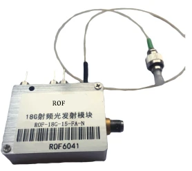
Description
2–18 GHz Radio-over-Fiber (RoF) Module
The 2–18 GHz Radio-over-Fiber (RoF) Module from Beijing Rofea Optoelectronics Co., Ltd. is designed for high‑performance analog RF signal transmission over optical fiber. Covering a continuous operating frequency range from 2 GHz up to 18 GHz, this module enables transparent transport of broadband microwave and RF signals with minimal distortion. It is well suited to demanding applications such as radar front‑haul, microwave delay lines, telemetry, tracking and command (TT&C), and long‑distance RF distribution in modern communication and test systems.
Engineered for large dynamic range and excellent linearity, the module supports input RF power levels from −70 dBm to +15 dBm with a typical gain of −30 dB. A high spurious‑free dynamic range (SFDR) of 103 dB/Hz2/3 at 1 GHz helps preserve signal integrity even in the presence of strong interferers, while a 1 dB compression point up to 20 dBm contributes to robust performance under high‑power conditions. In‑band flatness of ±1.8 dB across the operating band ensures consistent amplitude response over wide frequency sweeps, which is critical in applications such as broadband EW systems, multi‑carrier transmission, and high‑resolution test setups.
The optical subsystem is designed around standard telecom‑grade wavelengths, supporting operation at 1310 nm, 1550 nm, as well as DWDM and CWDM bands for dense or coarse wavelength‑division multiplexing. This allows straightforward integration into existing fiber infrastructures and multi‑channel RoF deployments. Typical side‑mode suppression ratio (SMSR) of 45 dB and optical isolation of 30 dB reduce noise and crosstalk, helping maintain low relative intensity noise (RIN) down to −145 dB/Hz. With an optical output power of 10 mW and a receiver responsivity up to 0.9 A/W, the link can be tailored to support long‑reach analog optical communication while maintaining a favorable signal‑to‑noise ratio.
Compared to many RoF solutions that are locked to specific digital formats or protocols, this module offers true format‑agnostic, transparent RF‑over‑fiber transport. Any modulation scheme that fits within the 2–18 GHz band can be conveyed, including AM, FM, PM, analog I/Q, as well as complex digital formats carried on RF or microwave carriers. This flexibility simplifies system design in laboratories, test ranges, and field deployments, where engineers can route RF directly over fiber without the added complexity and latency of digital conversion and processing stages.
The compact 95 mm × 60 mm × 21 mm footprint and low power consumption (up to 10 W from a single 5 V DC supply) make the module easy to integrate into space‑constrained equipment racks, airborne or mobile platforms, and outdoor enclosures. The small form factor also supports distributed architectures where multiple RF‑over‑fiber nodes are deployed close to antennas, sensors, or remote front‑ends, reducing coaxial cable losses and improving overall system noise performance.
In typical long‑distance analog optical communication applications, the RoF module allows RF signals that would suffer severe attenuation and phase distortion over long coaxial runs to be transported over fiber with low loss and improved electromagnetic immunity. This is especially valuable in TT&C and radar systems, where antennas may be located hundreds of meters or several kilometers away from control rooms or processing centers. Similarly, in microwave delay line implementations, the predictable propagation characteristics of optical fiber combined with the module’s flat RF response enable precise, stable delay paths over very long lengths, surpassing what is practical with purely RF hardware.
For test and measurement environments, research laboratories, and system integrators working in the 2–18 GHz range, this RoF module provides a ready‑to‑deploy building block to bridge RF and fiber domains. It can be employed to extend the reach of signal generators and analyzers, to centralize sensitive RF electronics while remote‑mounting antennas, or to distribute reference and local oscillator signals across large facilities. When compared with typical commercial RoF links, the combination of wideband coverage, high SFDR, strong SMSR, and compact, low‑power design positions this module as a versatile choice for both prototyping and production‑grade systems.
2 to 18GHz RoF Module Large Dynamic Range Low Power Consumption
Specifications
| Signaling Rate Per Lane (Transmitter): | Not Specified |
|---|---|
| Signaling Rate Per Lane (Receiver): | Not Specified |
| Lane Center Wavelength: | 1310 nm |
| Operating Frequency: | 2–18 GHz |
| Input RF Power: | -70 to 15 dBm |
| RF Gain: | -30 dB |
| In-band Flatness: | ±1.8 dB |
| 1 DB Compression Point: | 20 dBm |
| SFDR@1GHz: | 103 dB/Hz^(2/3) |
| IMD3: | 30 dBc |
| Operating Wavelength (system): | 1310 nm / 1550 nm / DWDM / CWDM |
| RIN: | ≤ -145 dB/Hz |
| SMSR: | 35–45 dB |
| Optical Isolation: | 30 dB |
| Transmitter Output Power: | 10 mW |
| Transmitter Operating Wavelength Range: | 1100–1700 nm |
| Receiver Response: | 0.85–0.9 A/W |
| Power Supply: | DC 5 V |
| Power Consumption: | ≤ 10 W |
| Dimension: | 95 × 60 × 21 mm |
Got questions about specs? Use the inquiry form to ask.
 Download Data Sheet

Features
- Wideband 2–18 GHz RF Operation – Supports broadband radio-frequency transmission across the full 2–18 GHz band, suitable for L-, S-, C-, and X‑band applications in modern radar, satellite, and wireless systems.
- Large Dynamic Range – Handles input RF powers from -70 dBm up to +15 dBm (with 1 dB compression point up to +20 dBm), enabling accurate transmission of both very weak and relatively strong microwave signals.
- High Linearity & Low Distortion – SFDR of 103 dB/Hz2/3 @ 1 GHz and IMD3 better than 30 dBc minimize nonlinear distortion, ensuring high‑fidelity analog microwave-over-fiber links.
- Excellent RF Response Flatness – In‑band flatness within ±1.8 dB across 2–18 GHz provides uniform gain and consistent system performance over the entire operating band.
- Transparent Signal Transmission – No signal format restriction; supports analog, digital, and complex modulation formats (e.g., QAM, OFDM, spread-spectrum) for flexible integration into diverse RF systems.
- Long‑Distance Analog Optical Links – Designed for long‑haul RF-over-fiber (RoF) transmission, enabling remote antenna placement and centralized processing with minimal RF cable loss.
- Low Power Consumption – Operates from a single DC 5 V supply with power consumption up to only 10 W, facilitating deployment in space‑constrained and power‑limited platforms.
- High-Performance Optical Front End – Supports 1310 nm, 1550 nm, DWDM and CWDM wavelengths with RIN down to -145 dB/Hz, SMSR up to 45 dB, and optical isolation ≥ 30 dB for stable and low‑noise operation in dense optical networks.
- High Optical Output Power – Transmitter output power up to 10 mW provides robust optical budget for extended fiber runs and link margin in demanding environments.
- High-Responsivity Receiver – Photodetector responsivity of 0.85–0.9 A/W maximizes electrical output for a given optical input, improving link efficiency and SNR.
- Compact Module Design – Small footprint of 95 × 60 × 21 mm simplifies integration into existing RF front ends, test setups, and system chassis.
- Ideal for Microwave Delay Lines – Fiber‑based RoF architecture is well suited for creating precise, low-loss microwave delay lines and true time delay networks in phased-array and radar systems.
- Optimized for TT&C and Telemetry – High linearity, wideband coverage, and large dynamic range support telemetry, tracking and command (TT&C) links and other mission‑critical ground and airborne communication systems.
- Reliable RF Signal Transport – Converts RF to optical and back with minimal degradation, enabling low‑loss, EMI‑immune RF signal transmission in harsh or high‑interference environments.
- Supports DWDM/CWDM Networking – Multi‑wavelength compatibility allows multiple independent RF channels to be multiplexed on a single fiber, increasing system capacity and scalability.
Applications
Applications of 2–18 GHz Radio-over-Fiber (RoF) Module
- Remote RF Signal Transmission and Distribution
Ideal for transporting 2–18 GHz RF signals from antennas or remote front-ends to centralized processing units over optical fiber, minimizing coaxial cable losses and preserving signal integrity over long distances. - Long-Distance Analog Optical Communication Links
Suited for analog fiber links in satellite ground stations, radar sites, and communication hubs where low distortion, high SFDR, and large dynamic range are required across microwave bands. - Microwave Delay Lines and Signal Conditioning
Used to implement long, stable delay lines for radar, EW (electronic warfare), and test systems by converting RF to optical domain, transmitting over fiber, and reconverting to RF with minimal added distortion. - Telemetry, Tracking, and Command (TT&C)
Well-suited for TT&C ground segment links that require transparent transport of modulated RF carriers over fiber, supporting precise tracking, command uplink, and telemetry downlink in 2–18 GHz bands. - Distributed Antenna Systems (DAS) and Remote Radio Heads
Enables radio-over-fiber distribution in in-building coverage, tunnels, stadiums, airports, and other large venues, carrying multiple RF services and standards simultaneously without format restrictions. - 5G/4G/Broadband Wireless Fronthaul
Applicable to analog fronthaul links between centralized baseband units (BBU) and remote radio units (RRU), especially in high-frequency bands (C-band and above), leveraging wide bandwidth and good flatness. - Radar Signal Transport and Remote Radar Siting
Supports distribution of radar transmit and receive signals between remote antennas and protected equipment shelters, improving electromagnetic isolation and allowing flexible radar array placement. - Electronic Warfare and ELINT/COMINT Systems
Suitable for transporting wideband RF signals in electronic intelligence and countermeasure systems from distributed antennas to central processing locations, where high SFDR and low noise are critical. - RF Test, Measurement, and Calibration Systems
Integrates into RF/microwave test setups requiring remote measurement points or shielded test environments, allowing instruments to be located away from harsh or cramped RF environments via fiber links. - Satellite Ground Station IF/RF over Fiber Links
Used to route L-, S-, C-, X-, and Ku-band IF or RF signals between antennas, control rooms, and monitoring centers, with excellent flatness ensuring accurate signal monitoring and processing. - Broadcast and Contribution Links
Applicable in professional broadcast contribution networks to carry microwave links (e.g., ENG/SNG receive signals) over fiber from rooftop or field antennas to central studios with minimal degradation. - Microwave Radio and Point-to-Point Backhaul Extension
Extends microwave backhaul reach by transporting RF over optical fiber between remote towers and central hubs, reducing RF cable losses and enabling centralized equipment architectures. - Phased Array Antenna and Beamforming Networks
Supports distribution of reference and RF signals to multiple antenna elements over fiber in phased arrays, radar, and advanced communication systems, maintaining amplitude and phase consistency across channels. - Secure and Low-EMI RF Links
Recommended for environments requiring low electromagnetic radiation and high immunity to EMI/RFI, such as defense, laboratories, and critical infrastructure, by replacing long RF cables with fiber. - Research, Education, and Laboratory Prototyping
A versatile platform for universities, research institutes, and development labs working on microwave photonics, radio-over-fiber systems, high-frequency communications, and advanced radar concepts.
Frequently Asked Questions
What is the 2–18 GHz RoF module and what applications is it designed for?
What are the key RF performance specifications of this 2–18 GHz radio-over-fiber module?
What optical interfaces and wavelengths does this RoF module support?
How does the module handle different RF signal formats and modulation schemes?
What are the power supply, power consumption, and physical dimensions of the module?
How does this 2–18 GHz RoF link compare to using coaxial cables for long-distance RF transmission?
What typical use cases and system examples benefit most from this 2–18 GHz RoF module?
Got more questions? Use the inquiry form to ask the supplier directly.
Similar Products


Your inquiry has been received.
Create an account by adding a password
Why create an account?
- Auto-complete inquiry forms
- View and manage all your past messages
- Save products to your favorites
- Close your account anytime — no hassle