
Description
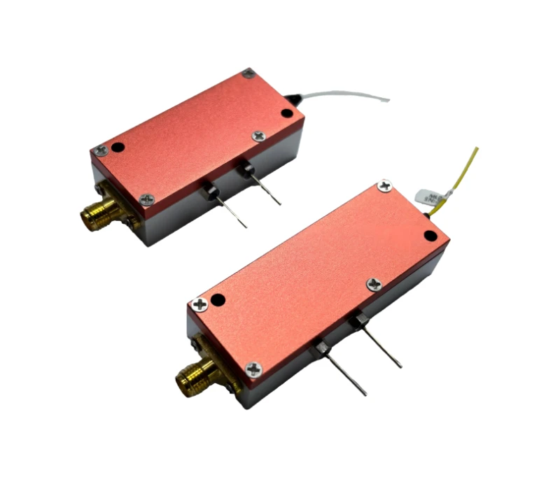
The Mini 0.6–6 GHz Analog Wideband Transceiver Module is a compact, cost‑effective fiber optic transmitter/receiver solution designed for demanding RF over fiber (RFoF) applications. Covering a continuous bandwidth from 0.6 GHz to 6 GHz, this module enables transparent transport of analog RF signals over single‑mode optical fiber while maintaining excellent linearity and a very high spurious‑free dynamic range (SFDR). Its flat frequency response and low noise performance make it well suited for modern broadband wireless, radar, and satellite ground station infrastructures where low distortion and stable amplitude response are critical.
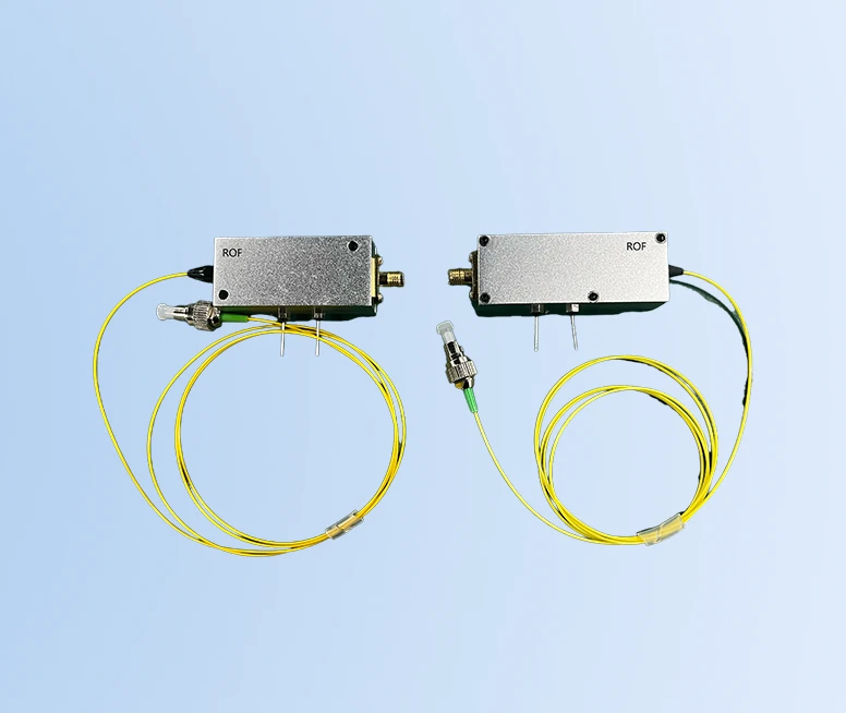
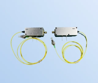
Designed as a matched transmit/receive pair, the module performs both RF‑to‑optical and optical‑to‑RF conversion to form a full two‑way RF link. On the RF side, standard 50 Ω SMA interfaces allow straightforward connection to existing RF front‑ends, test equipment, or distribution networks. On the optical side, the module uses 9/125 µm single‑mode fiber and operates at industry‑standard 1310 nm or 1550 nm wavelengths, ensuring compatibility with common telecom‑grade components and long‑haul fiber deployments. The integrated high‑performance InGaAs photodiode in the receiver and linear, optically isolated FP/DFB laser in the transmitter are engineered to preserve signal integrity over the full operating bandwidth.
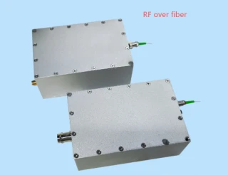
The transceiver is housed in a tight, cast metal enclosure that provides excellent shielding against electromagnetic interference and enhances thermal stability in field environments. Its compact footprint makes it easy to integrate into space‑constrained racks, radios, and embedded platforms, while the FC/APC optical connectors support low back‑reflection operation demanded by high‑performance analog links. With typical RF link gain around 0 dB and stable behavior across 0.6–6 GHz, the module behaves as a nearly transparent fiber extension of coaxial RF lines, significantly reducing loss over distance and simplifying remote antenna or sensor placement.
This wideband analog RFoF module is ideally suited for WiMAX and 4G LTE networks, 5G communication trials and deployments, shipborne RF distribution systems, and satellite earth station infrastructures where RF signals must be transported over tens to hundreds of meters or more without degrading dynamic range. It is also appropriate for distributed antenna systems (DAS), phased‑array radar distribution networks, remote LO / reference distribution, and cable replacement in test and measurement setups. The wide operating temperature range and robust design allow the module to be deployed in indoor equipment rooms as well as more challenging field or shipboard environments.
For system designers, the module offers a practical way to migrate from traditional coax‑based RF runs to fiber‑based links, reducing cable losses, weight, and susceptibility to electromagnetic interference. With support for 1310 nm and 1550 nm operation, standard single‑mode fiber, and FC/APC interfaces, it integrates seamlessly into existing optical infrastructures. Combined with its broad modulation bandwidth option (0.6–6 GHz configuration), the Mini Analog Wideband Transceiver Module provides a flexible platform for current and next‑generation RF communication and sensing systems that demand high linearity, wide bandwidth, and stable long‑distance transmission.
Mini 0.6–6GHz Analog Wideband RF Fiber Optic Transceiver Module
Specifications
| Signaling Rate Per Lane (Transmitter): | Not Specified |
|---|---|
| Signaling Rate Per Lane (Receiver): | Not Specified |
| Lane Center Wavelength: | 1310 nm |
| Bandwidth Response: | 0.6–6 GHz |
| High Frequency Cut-off: | 6 GHz |
| Low Frequency Cut-off: | 0.6 GHz |
| Supply Voltage (VCC): | 4.5–5 V |
| Supply Current (total Current, ICC): | 100 mA |
| Laser Output Power: | 2–4 mW |
| Transmitter Operating Wavelength: | 1310/1550 nm |
| Receiver Operating Wavelength: | 1310/1550 nm |
| Frequency Response (0.6–6 GHz): | ±1.5 to ±2 dB |
| Input RF Power: | -5 dBm |
| Input/Output Impedance (Z): | 50 Ω |
| Standing Wave Ratio (VSWR): | 1.5 |
| RF Link Gain: | -5 to 0 dB |
| RF Port: | SMA |
| Optical Fiber Type: | 9/125 μm single-mode fiber |
| Optical Connector: | FC/APC |
| Storage Temperature (TS): | -40 to 85 ℃ |
| Operating Temperature (TO): | -25 to 65 ℃ |
| DC Supply Voltage (VDP): | 4.5–5.5 V |
| Maximum RF Input (Tx): | 10 dBm |
| Maximum Optical Input (Rx): | 4 mW |
| Operating Wavelength Options (order Info): | 1310 nm or 1550 nm |
| Modulation Bandwidth Options (order Info): | 10–1200 MHz / 10–3000 MHz / 0.6–6 GHz |
| Encapsulation (order Info): | Module (M) |
| Connector Options (order Info): | FC/APC (FA) or user specified (SP) |
Got questions about specs? Use the inquiry form to ask.
 Download Data Sheet

Features
- Ultra-Wideband RF Coverage (0.6–6 GHz) – Supports a broad frequency range ideal for RF-over-fiber, 4G LTE, 5G, WiMAX, satellite, and shipborne RF distribution, reducing the need for multiple narrowband links.
- High Spurious-Free Dynamic Range (SFDR) – Optimized for low distortion analog transmission, enabling accurate transport of complex RF waveforms, multi-carrier signals, and high-order modulation formats over fiber.
- Flat Frequency Response (±1.5 to ±2 dB) – Provides excellent amplitude flatness from 0.6 GHz to 6 GHz, ensuring minimal signal ripple and consistent RF performance across the entire operating band.
- Integrated Transmit and Receive (Two-Way RF/Fiber Conversion) – A pair of modules forms a complete bidirectional RF-optical-RF link, simplifying RF-over-fiber system design for remote antenna and distributed RF applications.
- High-Performance Optical Front-End – Uses isolated FP/DFB laser diodes and InGaAs photodiodes for low noise, high linearity, and reliable analog modulation, delivering stable performance in demanding RF environments.
- Dual Standard Telecom Wavelengths (1310 nm / 1550 nm) – Supports operation at 1.3 μm and/or 1.5 μm over 9/125 μm single-mode fiber, compatible with standard telecom fiber infrastructure for long-distance RF-over-fiber links.
- Optimized Connectors for RF and Fiber – 50 Ω SMA RF ports and FC/APC fiber connectors provide low reflection, low loss interfaces that are widely used in professional RF and optical test, communication, and distribution systems.
- Compact Metal Module Package – Tight cast metal casing offers mechanical robustness and excellent electromagnetic shielding, minimizing RF leakage and external interference in dense system layouts.
- Low Power Consumption – Operates from a single 5 V DC supply with typical total current around 100 mA, enabling easy integration into space- and power-constrained remote units and outdoor enclosures.
- Stable RF Link Gain – Provides a typical RF link gain from -5 dB to 0 dB, supporting efficient RF power budgeting and predictable system-level performance without excessive external amplification.
- Low VSWR RF Interface – RF ports feature a typical standing wave ratio of about 1.5, helping to minimize reflections, improve matching with 50 Ω systems, and preserve signal integrity across the operating band.
- Wide Operating Temperature Range – Designed to work reliably from -25 °C to +65 °C (storage -40 °C to +85 °C), suitable for field-deployed, outdoor, and industrial RF-over-fiber installations.
- Built for RF-over-Fiber Applications – Specifically engineered for WiMAX, 4G LTE, 5G communication links, satellite earth stations, and shipborne RF distribution, offering carrier-grade performance in compact form.
- Configurable Modulation Bandwidth Options – Available modulation bandwidth configurations (10–1200 MHz, 10–3000 MHz, 0.6–6 GHz) allow tailoring the module to specific RF bands and system requirements.
- Easy System Integration – Module encapsulation with clearly defined electrical, RF, and optical interfaces simplifies integration into OEM platforms, rack systems, test setups, and custom RF distribution networks.
Applications
- 5G New Radio (NR) Distributed Antenna Systems – RF over fiber fronthaul and backhaul links for sub‑6 GHz 5G networks, C‑band small cells, and remote radio head connections requiring low noise and high SFDR.
- 4G LTE and WiMAX Remote Radio Links – Extending LTE and WiMAX coverage from baseband units to remote antennas via RFoF (Radio over Fiber) to minimize coaxial cable loss and preserve flat frequency response across 0.6–6 GHz.
- Satellite Earth Station IF and L‑Band Transport – Optical transport of satellite L‑band and IF signals between outdoor antenna units (LNB/BUC) and indoor equipment, improving link budget and immunity to EMI over long distances.
- Shipborne RF Distribution Systems – Distribution of mission‑critical RF, navigation, and communications signals over fiber on ships and offshore platforms, leveraging the metal case, SMA ports, and FC/APC connectors for robust marine environments.
- Radar and EW (Electronic Warfare) Fiber Links – Low‑distortion transport of radar IF and RF signals over fiber for phased‑array radars, electronic support measures (ESM), and electronic countermeasures (ECM) systems.
- Radio over Fiber (RoF) for DAS and In‑Building Coverage – Feeding indoor distributed antenna systems in stadiums, tunnels, skyscrapers, airports, and campuses with wideband RF signals over single‑mode fiber.
- RF Test, Measurement, and Calibration Setups – Routing RF signals between shielded rooms, remote test heads, anechoic chambers, and centralized instrumentation without performance degradation from long coax runs.
- Microwave and Millimeter‑Wave System IF Transport – Carrying down‑converted intermediate frequency signals (0.6–6 GHz) over fiber in microwave backhaul, point‑to‑point links, and mmWave front‑end architectures.
- Broadcast and Media Contribution Links – High‑fidelity transmission of RF carriers for satellite news gathering (SNG), OB vans, and contribution/backhaul links where low spurious‑free dynamic range and flat response are critical.
- Secure Government and Defense Communications – Covert, EMI‑immune transport of tactical RF communications over optical fiber in command posts, shelters, and hardened facilities.
- Remote Antenna and Sensor Placement – Fiber extension for antennas, RF sensors, and monitoring probes located far from the central station, enabling high‑dynamic‑range measurements in noisy or high‑voltage environments.
- GNSS, GPS, and Timing Signal Distribution – Optical distribution of L‑band GNSS/GPS reference signals from rooftop antennas to multiple indoor receivers without phase degradation or RF cable loss.
- Cellular Repeater and Macro/Micro Cell Extension – Feeding RF repeaters and microcells in rural or difficult terrain through low‑loss RF over fiber links across several kilometers.
- Laboratory and R&D Wideband RF Links – Flexible, low‑cost RF–optical–RF paths for research on wideband communications, optical modulation, and system prototyping in universities and R&D labs.
- Industrial and Utility Monitoring Systems – Fiber transmission of RF monitoring, control, and telemetry signals in substations, power plants, and harsh industrial facilities with strong electromagnetic interference.
- Aerospace and Avionics Test Benches – Transport of RF test signals between aircraft or spacecraft subsystems and ground test equipment, reducing cable weight and susceptibility to interference.
- Medical and MRI‑Compatible RF Links – RF over fiber connections for MRI coils, medical imaging, and hospital RF monitoring where non‑metallic, EMI‑immune signal transport is essential.
- Building and Campus‑Wide RF Monitoring Networks – Centralized spectrum monitoring and interference detection using remote RF probes connected to a main analysis center over single‑mode fiber.
- Defense Training and Simulation Systems – Distribution of live and simulated RF scenarios over fiber to multiple nodes in training ranges and simulators while maintaining linearity and dynamic range.
- General Wideband RF over Fiber Infrastructure – Any application requiring 0.6–6 GHz, low‑distortion, bidirectional RF to optical and optical to RF conversion using FC/APC single‑mode fiber and 50 Ω SMA interfaces.
Frequently Asked Questions
What is the Mini 0.6–6 GHz Analog Wideband Transceiver Module and what does it do?
What are the key specifications and performance characteristics of this 0.6–6 GHz RF over fiber module?
How do I integrate and power the Mini 0.6–6 GHz Analog Wideband Transceiver Module in my RF over fiber system?
What applications is this 0.6–6 GHz analog wideband transceiver module suitable for?
What are the ordering options (wavelength, bandwidth, connectors, package) for the Rofea Mini RF over fiber module?
What type of fiber and optical connectors are required for this RF over fiber transceiver?
What are the operating limits and reliability considerations for long‑term use of the Mini 0.6–6 GHz RF over fiber module?
Got more questions? Use the inquiry form to ask the supplier directly.
Similar Products


Your inquiry has been received.
Create an account by adding a password
Why create an account?
- Auto-complete inquiry forms
- View and manage all your past messages
- Save products to your favorites
- Close your account anytime — no hassle