


Description
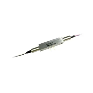
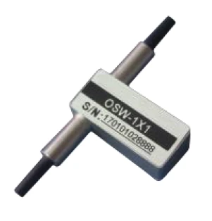
The 1x2 Mechanical Optical Switch is a compact, high‑performance fiber routing component designed for demanding optical test, sensing, and network monitoring applications. With a wide operating wavelength range from 1260–1620 nm for single‑mode fibers and 850 nm for multimode fibers, this switch supports common telecommunication bands as well as short‑wavelength datacom and sensor systems. Its small footprint (27.0 mm × 12.0 mm × 8.2 mm) allows easy integration into dense instrumentation, transceiver modules, and rack‑mount systems where space and optical performance are equally critical.
Insertion loss is kept extremely low, at ≤0.6 dB, which helps preserve system power budgets and extend reach without the need for additional amplification. The switch offers excellent wavelength, polarization, and temperature stability, with wavelength dependent loss ≤0.25 dB, polarization dependent loss ≤0.05 dB, and temperature dependent loss ≤0.20 dB. These characteristics make it suitable for precision measurement setups and high‑accuracy optical paths where even minor variations can impact overall performance. An epoxy‑free optical path further enhances long‑term reliability and minimizes outgassing and contamination in sensitive environments such as laboratories and clean‑room instrumentation.
For systems requiring strong signal fidelity, the 1x2 Mechanical Optical Switch delivers a high return loss of ≥50 dB for single‑mode and ≥30 dB for multimode configurations, reducing back‑reflections that can interfere with lasers, detectors, or interferometric setups. Crosstalk performance is equally robust, with ≥55 dB isolation in single‑mode and ≥35 dB in multimode operation, ensuring that optical channels remain cleanly separated. This combination of low loss, high isolation, and low back‑reflection supports applications such as coherent transmission, optical time‑domain reflectometry (OTDR), and precision end‑to‑end loss measurement.
The device supports both latching and non‑latching configurations with operating voltages of 3 V or 5 V, allowing designers to match drive requirements to their system electronics. Latching types maintain their state without continuous drive current, which is advantageous in power‑sensitive or battery‑operated equipment. Non‑latching options are ideal where frequent switching and straightforward control logic are priorities. Clearly defined pin configurations for the electric drive and state sensor pins simplify PCB layout and integration with microcontrollers, FPGAs, and dedicated switch drivers commonly used in optical modules.
With a switch time of ≤8 ms, the 1x2 mechanical design offers a good balance between speed and stability, making it appropriate for dynamic optical routing, automated test setups, and fiber‑based sensor multiplexing. Repeatability of ≤±0.02 dB ensures that repeated switching events do not introduce measurable deviations, which is essential for calibrated measurement systems and closed‑loop monitoring platforms. The switch is rated for at least 107 operations, providing a long service life even under frequent actuation cycles typical of automated test equipment and network surveillance applications.
The operating temperature range of −20 °C to +70 °C and storage range of −40 °C to +85 °C allow deployment in a wide variety of environments, from laboratory benches and production lines to controlled field enclosures. The maximum optical power handling of ≤500 mW supports most standard telecom and datacom‑class sources, including many laser diodes and fiber‑amplified links. Available fiber types include standard single‑mode (9/125 µm) and multimode (50/125 µm, 62.5/125 µm), with options for customized fibers on request, ensuring compatibility with existing network infrastructures and sensor platforms.
To streamline installation and system design, the 1x2 Mechanical Optical Switch can be configured with a range of fiber jacket types, cable lengths, and industry‑standard connectors. Typical options include bare 250 µm fibers or 900 µm buffered pigtails, with standard lengths such as 0.5 m, 1.0 m, and 1.5 m. Connector interfaces can be tailored to the target system, including FC/PC, FC/APC, SC/PC, SC/APC, LC/PC, LC/APC, or other connector types as needed. This flexibility makes the switch suitable for instrumentation front‑ends, optical distribution frames, test harnesses, and embedded OEM subsystems, enabling efficient deployment in both existing and new optical architectures.
Whether used in optical network monitoring, fiber‑based sensing arrays, laboratory instrumentation, or end‑to‑end link characterization, this 1x2 Mechanical Optical Switch offers a robust balance of low insertion loss, high isolation, fast and repeatable switching, and durable construction.
1x2 Mechanical Fiber Optic Switch Low Loss High Isolation 1260 1620 nm
Specifications
| Number Of Ports: | 1 – 2 |
|---|---|
| Wavelength Range: | 1260 – 1620 nm |
| Insertion Loss (typical): | 0.6 dB |
| Return Loss: | 50 dB |
| Product: | 1x2 Mechanical Optical Switch |
| Operating Wavelength (SM): | 1260~1620 nm |
| Operating Wavelength (MM): | 850 nm |
| Insertion Loss: | ≤0.6 dB |
| Wavelength Dependent Loss: | ≤0.25 dB |
| Polarization Dependent Loss: | ≤0.05 dB |
| Temperature Dependent Loss: | ≤0.20 dB |
| Return Loss (SM): | ≥50 dB |
| Return Loss (MM): | ≥30 dB |
| Cross Talk (SM): | ≥55 dB |
| Cross Talk (MM): | ≥35 dB |
| Switch Time: | ≤8 ms |
| Repeatability: | ≤±0.02 dB |
| Durability: | ≥10^7 times |
| Operating Voltage: | 3 V or 5 V |
| Switch Type: | Non-latching or Latching |
| Operating Temperature: | -20 to +70 °C |
| Storage Temperature: | -40 to +85 °C |
| Maximum Optical Power: | ≤500 mW |
| Dimensions: | L27.0 × W12.0 × H8.2 mm |
| Available Test Wavelengths: | 850 nm, 1310 nm, 1550 nm, 1310 & 1550 nm, others |
| Available Fiber Types: | SM 9/125, MM 50/125, MM 62.5/125, others |
| Available Tube Types: | Φ250 μm, Φ900 μm |
| Standard Fiber Lengths: | 0.5 m, 1.0 m, 1.5 m |
| Available Connectors: | None, FC/PC, FC/APC, SC/PC, SC/APC, LC/PC, LC/APC, others |
Got questions about specs? Use the inquiry form to ask.
 Download Data Sheet

Features
- 1x2 Mechanical Optical Switch for Singlemode and Multimode Systems
Optimized for 1260–1620 nm SM and 850 nm MM operation, ideal for a wide range of telecom, datacom, test & measurement, and fiber sensing applications. - Low Insertion Loss for Accurate Signal Routing
Delivers typical insertion loss of ≤0.6 dB, minimizing link budget penalties and enabling precise end-to-end loss measurements and optical network monitoring. - High Isolation and Low Crosstalk
Ensures signal integrity with crosstalk ≥55 dB (SM) and ≥35 dB (MM), providing excellent channel separation in dense fiber networks and instrumentation systems. - Excellent Return Loss Performance
High return loss of ≥50 dB (SM) and ≥30 dB (MM) reduces back‑reflection, improving performance in high‑speed, high‑sensitivity optical links. - Ultra-Stable, Low-Drift Switching
Features wavelength dependent loss ≤0.25 dB, polarization dependent loss ≤0.05 dB, and temperature dependent loss ≤0.20 dB, ensuring high stability and repeatability over time and temperature. - Fast Switching for Dynamic Optical Routing
Mechanical design delivers switching time ≤8 ms, suitable for real-time protection switching, network reconfiguration, and fiber path selection. - Exceptional Repeatability and Long Lifetime
High-precision mechanism offers repeatability ≤±0.02 dB and durability of ≥107 cycles, ideal for automated test setups and continuous network monitoring. - Epoxy‑Free Optical Path
Uses an epoxy‑free optical path to reduce contamination and aging effects, providing long‑term reliability for high‑power and sensitive measurement environments. - Supports Up to 500 mW Optical Power
Handles optical power levels of ≤500 mW, suitable for use with high‑power sources commonly used in R&D labs and field instrumentation. - Latching and Non‑Latching Configurations
Available in both latching and non‑latching versions to match system requirements for power‑fail safety or state retention without continuous drive current. - Flexible Operating Voltage Options
Designed for 3 V or 5 V electrical drive, enabling easy integration with embedded controllers, test instruments, and network equipment. - Wide Operating and Storage Temperature Ranges
Reliable operation from -20 °C to +70 °C and storage from -40 °C to +85 °C, making it suitable for both lab environments and harsh field conditions. - Compact Miniature Package
Small footprint of L27.0 × W12.0 × H8.2 mm saves space in dense optical modules, rack systems, and portable test equipment. - Versatile Fiber and Connector Options
Supports SM 9/125, MM 50/125, MM 62.5/125, and custom fibers, with connector choices including FC/PC, FC/APC, SC/PC, SC/APC, LC/PC, LC/APC, or bare fiber to fit existing infrastructure. - Multiple Wavelength Configurations
Standard wavelengths include 850 nm, 1310 nm, 1550 nm, and dual‑window 1310/1550 nm, with other wavelengths available on request for specialized applications. - Robust Fiber Handling and Packaging
Available with φ250 μm or φ900 μm fiber jackets and standard fiber lengths (e.g., 0.5 m, 1.0 m, 1.5 m), providing flexibility for inside‑instrument routing or panel connections. - Integrated Electrical Pin Configuration
Clearly defined pinout for electric drive and state sensor simplifies PCB design and system‑level control in both latching and non‑latching modes.
Applications
- Optical Network Protection and Restoration
- Automatic fiber path switching in metro and long-haul networks
- Protection switching between working and backup fibers in DWDM and CWDM systems
- Reconfiguration of optical add/drop multiplexers (OADMs) and ROADMs
- Redundant fiber routing in data center interconnects and enterprise backbones
- Optical Network Monitoring and Test
- Remote fiber monitoring with OTDRs and optical spectrum analyzers
- End-to-end loss and continuity measurements in field test instruments
- Automatic selection of test ports in optical test beds and lab setups
- Network performance verification in manufacturing and production lines
- Instrumentation and Lab Automation
- Port routing in optical power meters, light sources, and BER testers
- Signal path selection in coherent and direct-detection test systems
- Configurable optical paths in R&D fiber optic experiments
- Automated measurement systems requiring repeatable low-loss switching
- Fiber Optic Sensing Systems
- Multiplexing of distributed fiber sensors (DTS, DAS, DSS, DFOS)
- Channel selection for FBG (Fiber Bragg Grating) sensing arrays
- Switching between reference and measurement sensors for calibration
- Structural health monitoring in civil, aerospace, and energy applications
- Industrial and Environmental Monitoring
- Fiber-based temperature, strain, and pressure sensing networks
- Process monitoring in oil & gas, power plants, and mining
- Harsh-environment sensor routing where electrical sensors are impractical
- Long-distance sensing links with high isolation between channels
- Telecommunications and Access Networks
- Fiber path control in central offices and remote nodes
- Backup path selection in PON, FTTx, and broadband access networks
- Line testing and service verification without disrupting live traffic
- Migration between legacy and upgraded optical links
- Data Centers and Enterprise Networks
- Bypass switching for network equipment maintenance or failure
- Out-of-band monitoring and tapping for performance analysis
- Dynamic reconfiguration of lab and validation networks
- Multi-path connectivity for high-availability architectures
- Optical Module and Device Testing
- Automated test setups for transceivers, splitters, and amplifiers
- Burn-in and reliability testing with repeated optical path changes
- Switching between golden reference and DUT (Device Under Test)
- Multi-wavelength, multi-port qualification of fiber optic components
- Medical and Bio-Photonics
- Routing light in diagnostic and imaging systems (OCT and spectroscopy)
- Sharing light sources between multiple imaging probes or channels
- Calibration paths between reference and sample fibers
- Low-loss fiber switching in minimally invasive optical instruments
- Laser Delivery and Measurement
- Selection between multiple laser sources or output ports
- Distribution of a single laser to different test stations
- Laser power monitoring and feedback paths with minimal insertion loss
- Safe routing of moderate-power laser signals (up to 500 mW)
- Research, Education, and Prototyping
- Flexible optical routing in university and research laboratories
- Demonstration setups for optical communications and photonics teaching
- Rapid prototyping of switching and protection schemes
- Experimental validation of new fiber-based sensor concepts
- Security and Surveillance Systems
- Fiber path management for perimeter and pipeline monitoring systems
- Redundant links for critical security communications
- Switching between primary and backup monitoring fibers
- Integration with distributed acoustic sensing for intrusion detection
- Broadcast and AV Fiber Links
- Fiber route selection for studio, stadium, and event connectivity
- Backup and failover paths for live broadcast feeds
- Shared fiber infrastructure for multiple cameras and signal paths
- Low-loss switching for high-bandwidth video over fiber systems
- Aerospace, Defense, and Transportation
- Redundant optical links in avionics and shipboard networks
- Fiber switching in radar, lidar, and sensor fusion platforms
Frequently Asked Questions
What is a 1x2 mechanical optical switch and how does it work?
What are the key optical performance specifications of this 1x2 mechanical fiber optic switch?
What is the difference between latching and non‑latching versions of this 1x2 optical switch?
What fibers, wavelengths, and connector options are available for this mechanical optical switch?
How fast does the 1x2 mechanical optical switch operate and what is its reliability?
What are the electrical drive requirements and pin configurations for this 1x2 optical switch?
In what applications is this 1x2 mechanical optical switch typically used and how should it be installed?
Got more questions? Use the inquiry form to ask the supplier directly.
Similar Products

Your inquiry has been received.
Create an account by adding a password
Why create an account?
- Auto-complete inquiry forms
- View and manage all your past messages
- Save products to your favorites
- Close your account anytime — no hassle