
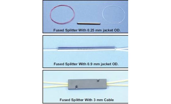

Description
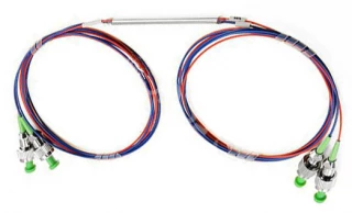
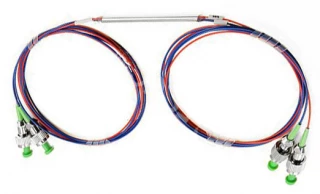
Fused fiber optic couplers are fundamental components for splitting or combining optical signals in a wide range of photonic systems. By carefully fusing and tapering two or more optical fibers together, these couplers enable reliable power distribution and signal routing in a compact, mechanically robust package. They are widely used in test and measurement setups, optical communication networks, fiber sensors, and laboratory research where stable and predictable optical power management is required.
In a fused coupler, the cores of two fibers are brought into close proximity and thermally fused over a controlled taper region. As light propagates through this interaction zone, a fraction of the optical power is transferred from one fiber to the other. By precisely controlling the geometry of the fused region, manufacturers can design devices with specific splitting ratios such as 50/50, 90/10, or other custom configurations. This technology supports standard 1x2 and 2x2 couplers, as well as more complex NxM structures (for example 1x3 or 1x4) that are tailored for specialized network architectures or multi-channel distribution.
Singlemode fused couplers support only one propagation mode, which eliminates mode dependency effects that are inherent to multimode devices. This makes singlemode variants particularly suitable for high-performance communication links, precision measurements, and systems requiring stable splitting ratios over time and varying launch conditions. However, singlemode fused couplers are inherently wavelength dependent. Even a relatively small wavelength shift, on the order of 10 nm, can noticeably alter the coupling ratio. For that reason, specifying and operating the coupler at a well-defined wavelength is essential for accurate power budgeting and repeatable system behavior.
Multimode fused couplers, in contrast, support multiple propagating modes and therefore exhibit mode-dependent performance. The splitting ratio can vary depending on which modes are excited at the input, as some modes couple more efficiently than others within the fused region. To achieve a stable and predictable splitting ratio, these couplers are typically optimized assuming an equilibrium mode distribution, often achieved by using incoherent sources such as LEDs, employing mode scramblers, or adding sufficient fiber length prior to the coupler. When these conditions are met, multimode fused couplers provide a cost‑effective solution for power splitting in short‑reach networks, illumination systems, and general-purpose fiber setups.
Polarization maintaining (PM) fused couplers are also available, fabricated from PM fiber to support applications where polarization state is important. However, the fusion and tapering process introduces a localized region where the polarization properties are not perfectly preserved. At this fusion point, sensitivity to environmental influences such as temperature changes and mechanical vibration can degrade polarization extinction and stability. Because of this, PM fused couplers are not the optimal choice for highly demanding polarization-sensitive systems such as precision interferometry or polarization-based sensing. In those scenarios, designers often turn to hybrid micro‑optic beam splitters or similar free‑space approaches that provide better polarization control.
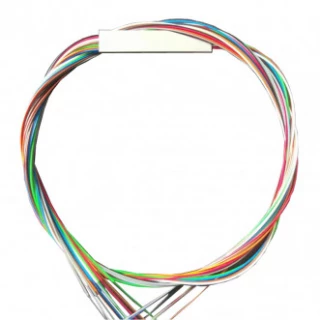
These fused couplers are offered over a broad wavelength range, commonly spanning from the visible region to the near‑infrared (approximately 400–2000 nm), covering popular telecom windows and numerous laser lines. A range of fiber sizes and numerical apertures can be selected to match existing infrastructure, including standard singlemode and multimode fibers. Customers can specify target splitting ratios, operating wavelengths, and connector types to fit their integration requirements. Available pigtail formats include bare 250 µm fibers, 0.9 mm jacketed fibers, and ruggedized 3 mm cabled versions, allowing straightforward deployment from benchtop experiments to field installations where mechanical protection and strain relief are needed.
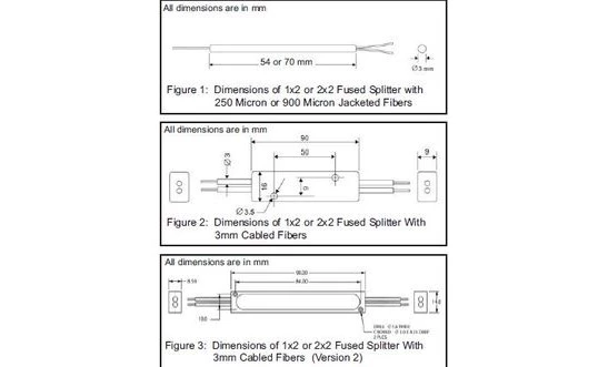
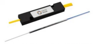
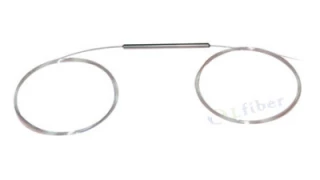
Mechanically, fused couplers are designed for compactness and durability. The fused region is encapsulated in a small protective housing whose length is typically on the order of a few centimeters, enabling easy routing and bundling within patch panels, test stations, and instrument enclosures. This small footprint, combined with low insertion loss, good uniformity among output ports, and high directivity, makes fused couplers a versatile choice where space and optical performance must be balanced.
Fused Couplers – Fiber Optic
Specifications
| Type: | Other / Not Specified |
|---|---|
| Configuration: | Other |
| Splitting Ratio: | Other / Not specified |
| Wavelength: | 1550 nm |
| Fiber Type: | Single-mode (SM), PMI125/250, PMI80/165 |
| Connector Type: | FC, SC, ST, LC |
| Housing Material: | Stainless Steel, Plastic, Aluminum |
| Wavelength Range: | 400–2005 nm |
| Configuration: | 1x2, 2x2 (N×M such as 1x3, 1x4 on request) |
| Fiber Types: | Singlemode, Multimode, Polarization maintaining |
| Jacket Outer Diameter Options: | 0.25 mm, 0.9 mm, 3 mm |
| Package Length: | 54 mm or 70 mm |
| Mode Dependence: | Singlemode: not mode dependent; Multimode: mode dependent |
| Wavelength Dependence: | High; 10 nm wavelength change can significantly alter splitting ratio |
Got questions about specs? Use the inquiry form to ask.
 Download Data Sheet

Features
- Low Insertion Loss & High Performance – Optimized fused biconic taper (FBT) design ensures minimal excess loss for efficient signal splitting and combining in demanding fiber optic networks.
- Wide Operating Wavelength Range (400–2005 nm) – Supports visible and infrared bands, making these fused couplers ideal for telecom, CATV, test & measurement, fiber laser delivery, and laboratory applications.
- Available in Singlemode, Multimode & PM Fiber Versions – Choose the fiber type that matches your system: low‑mode‑dependent singlemode for stable splitting ratios, multimode for high‑power / short‑reach systems, and polarization maintaining (PM) options where polarization sensitivity is acceptable.
- Custom Splitting Ratios – Standard 50/50, 70/30, 90/10 and other tailored coupling ratios available to match specific power budgeting and monitoring requirements.
- One‑by‑Two, Two‑by‑Two and N‑by‑M Configurations – Standard 1×2 and 2×2 fused couplers, with 1×3, 1×4 and other N×M splitter/combiner configurations offered on request for flexible network design.
- Broad Bandwidth with Good Uniformity – Engineered for consistent splitting over the specified wavelength window, providing uniform performance across channels and minimizing imbalance between output ports.
- High Directivity & Low Back‑Reflection – Excellent isolation between input and output ports reduces crosstalk and reflected power, improving system signal‑to‑noise ratio and measurement accuracy.
- Compact & Rugged Package – Small-form cylindrical fused region with industry‑standard lengths (typically 54 or 70 mm) for easy integration into crowded patch panels, modules, instruments, and OEM assemblies.
- Multiple Fiber Jacket Options – Available with 0.25 mm bare fiber, 0.9 mm tight‑buffered, or 3 mm jacketed cable to suit direct splicing, routing in enclosures, or robust field‑deployable cabling.
- Connectorized or Bare Fiber Termination – Delivered with a wide range of polish and connector styles (e.g. FC/PC, FC/APC, SC/PC, SC/APC, ST, LC) or with bare fiber pigtails for fusion splicing into existing networks.
- Low Cost Solution for Signal Splitting & Combining – Fused coupler technology offers a highly cost‑effective alternative to bulk‑optic splitters, ideal for volume deployment in FTTx, PON, DAS and monitoring applications.
- Mode‑Optimized Multimode Designs – Multimode couplers are designed for equilibrium mode distribution, providing stable splitting ratios when used with LEDs, mode scramblers, or sufficient fiber length ahead of the coupler.
- Application‑Specific Wavelength Optimization – Singlemode couplers are carefully tuned to a specified center wavelength (e.g. 1310 nm, 1550 nm, 1064 nm) to achieve the desired coupling ratio, critical for DWDM, CWDM and narrowband laser systems.
- Telecom‑Grade Reliability – Manufactured to stringent optical component standards with robust fusion joints that withstand temperature changes, vibration and mechanical stress in long‑term field use.
- Ideal for Splitting, Combining & Monitoring – Suitable for power sharing in fiber networks, combining signals from multiple sources, tapping a small portion of power for monitoring, and routing light in test setups and interferometric systems.
Applications
Fused couplers are widely used in optical fiber systems to split or combine light with low loss and high reliability. Thanks to their small size, broad wavelength coverage (400–2005 nm), and availability in singlemode, multimode, and polarization-maintaining (PM) versions, they support a broad range of industrial, telecom, laboratory, and sensing applications.
Telecommunications and Data Networks
- Optical signal splitting in access networks (FTTx, FTTH) – Distribute downstream signals from an optical line terminal (OLT) to multiple optical network units (ONUs) in passive optical networks (PON), including GPON, EPON, and xPON architectures.
- Network monitoring and tapping – Divert a small portion of the optical power to an optical power meter, optical spectrum analyzer (OSA), or network analyzer for performance monitoring, bit-error-rate testing, and non-intrusive network surveillance.
- Redundant and ring architectures – Split and recombine signals in ring, mesh, and redundant fiber paths to increase system reliability and enable automatic protection switching.
- Signal distribution in metro and long-haul links – Provide controlled splitting ratios for adding monitoring channels, pilot tones, or out-of-band management channels along transmission spans.
- Local area and enterprise networks – Implement point-to-multipoint distribution within data centers, campus networks, and industrial Ethernet over fiber systems.
Fiber Optic Test, Measurement, and R&D
- Optical power monitoring – Use low-ratio fused couplers (for example 99/1, 95/5) to monitor laser power, amplifier output, or system stability without significantly disturbing the main optical path.
- Reference and calibration splitters – Split a stable reference source into multiple paths for calibration of optical power meters, spectrometers, and photodetectors.
- Laboratory interferometer setups – Form the basis of Mach–Zehnder, Michelson, Sagnac, or common-path interferometers in fiber-based test benches and research experiments.
- Coherent detection experiments – Combine local oscillator and signal paths or divide optical signals for balanced photodetection in coherent communication and heterodyne/homodyne measurement systems.
- Mode scrambling and modal studies – In multimode systems, use couplers in conjunction with long fiber runs and mode scramblers to investigate mode distribution, differential mode delay, and bandwidth performance.
- Broadband spectroscopy benches – Split broadband sources (supercontinuum, ASE, LEDs) into reference and sample arms for spectroscopic characterization, absorption measurements, and component testing.
Fiber Lasers, Amplifiers, and Light Sources
- Pump and signal combining – Combine outputs of multiple pump diodes or split pump power among several gain fibers in erbium-doped fiber amplifiers (EDFAs), ytterbium-doped, and other rare-earth-doped fiber lasers.
- Power sampling in high-power lasers – Divert a small fraction of output power for real-time monitoring, feedback stabilization, and laser diagnostics while transmitting most power to the application.
- Laser seeding and injection locking – Split seed laser power into multiple amplifier stages or distribute a master oscillator to several slave lasers for phase-locked or frequency-stabilized systems.
- Multi-port output distribution – Create one-to-many outputs from a single laser source for parallel processing, illumination, or multi-channel excitation in instrumentation.
- Gain flattening and spectral control setups – Use couplers in conjunction with filters, gratings, or tunable elements to realize feedback loops and spectral shaping paths in fiber laser cavities.
Fiber Optic Sensing and Instrumentation
- Interferometric fiber sensors – Implement sensing interferometers (Mach–Zehnder, Michelson, Fabry–Perot, and Sagnac) for precise measurement of strain, temperature, vibration, pressure, and acoustic signals.
- Fiber Bragg grating (FBG) interrogation – Split light between reference and sensing FBG arrays and combine reflected or transmitted signals for multiplexed structural health monitoring.
- Distributed sensing systems – Distribute optical power to multiple sensing branches in distributed temperature sensing (DTS), distributed acoustic sensing (DAS), and distributed strain sensing (DSS) using OTDR or OFDR techniques.
Frequently Asked Questions
What is a fused fiber optic coupler and how does it work?
What is the difference between singlemode and multimode fused couplers?
How wavelength dependent are fused couplers and which wavelengths are available?
Can fused couplers be used with polarization maintaining (PM) fiber for polarization‑sensitive applications?
What configurations, splitting ratios, and fiber types are available for fused couplers?
What package sizes and mechanical options are available for fused splitters?
When should I use a fused coupler versus a micro‑optic beam splitter/combiner?
Got more questions? Use the inquiry form to ask the supplier directly.
Similar Products
Your inquiry has been received.
Create an account by adding a password
Why create an account?
- Auto-complete inquiry forms
- View and manage all your past messages
- Save products to your favorites
- Close your account anytime — no hassle