


Description
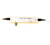
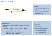
The R-PM-10-10G is a high‑performance lithium niobate (LiNbO3) phase modulator specifically optimized for operation around in the near infrared range with up to 10 GHz modulation bandwidth. Designed for demanding research and industrial environments, this device enables precise phase control of continuous‑wave and pulsed lasers used in high‑speed optical communication testbeds, coherent detection schemes, advanced sensing, and radio‑over‑fiber experiments. By combining low half‑wave voltage with low insertion loss and excellent polarization extinction, the modulator delivers stable, repeatable performance in long‑term setups and tightly integrated optical systems.
Leveraging Ti‑diffused and annealed proton‑exchanged (APE) waveguide technology in LiNbO3, the R-PM-10-10G waveguide structure offers robust physical and chemical stability comparable to leading commercial phase modulators used in telecom and scientific markets. The device operates over a broad wavelength window from 980 nm to 1150 nm (centered at 1064 nm), providing flexibility for use with Nd:YAG, Yb‑doped fiber lasers, and other near‑infrared sources. Typical insertion loss is around 3–3.5 dB, with an optical return loss of about −45 dB, which supports clean interferometric measurements and helps maintain high system signal‑to‑noise ratio.
The R-PM-10-10G is built around a polarization‑maintaining (PM) fiber pigtail on both input and output, ensuring that the modulator preserves the polarization state required for coherent systems and interferometric applications. The polarization extinction ratio is typically above 20 dB, aligning with performance levels expected in modern PM LiNbO3 modulators used in quantum optics and precision metrology. The standard configuration uses 980 nm PM fiber (125/250 µm), and the output can be provided as PM or, when needed, as single‑mode fiber to ease integration with existing laser and detection chains. Common connector options include FC/PC or FC/APC to match laboratory and field‑deployment setups.
On the electrical side, the modulator provides a −3 dB RF bandwidth of approximately 10–12 GHz, making it suitable for high‑speed phase modulation, frequency shifting, and complex waveform synthesis in microwave photonics. The half‑wave voltage Vπ at 50 kHz is typically 3.5–4.0 V, which enables efficient phase modulation with moderate‑power RF drivers. With a characteristic input impedance of 50 Ω and an SMA‑female RF connector, the device can be directly interfaced with most commercial RF signal generators, vector network analyzers, and high‑frequency amplifiers. Electrical return loss is around −10 to −12 dB, consistent with comparable 10 GHz LiNbO3 phase modulators widely used in research laboratories.
The R-PM-10-10G is engineered for reliable operation in a variety of environments, featuring an input optical power handling capability up to 20 dBm and maximum RF input power around 28 dBm. The specified operating temperature range of −10 °C to +60 °C, combined with a storage range from −40 °C to +85 C and 5–90 % relative humidity tolerance, supports both benchtop and system‑embedded deployment. These characteristics make the device well suited for long‑term experiments such as quantum key distribution, coherent lidar and laser sensing, and stability‑critical interferometric measurements where reproducible phase control at 1064 nm is essential.
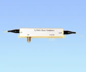
Mechanically, the modulator follows the standard integrated LiNbO3 package format, with clearly defined ports for optical input, optical output, RF input, and bias control. The RF port is implemented with an SMA‑female connector, and bias pads are provided for fine phase tuning or offset compensation when used in more complex modulation schemes. This layout is compatible with common RF driver and bias control boards used across the photonics industry, making integration straightforward for users upgrading from other phase modulators or designing new high‑speed photonic systems.
Overall, the R-PM-10-10G offers a balanced combination of low Vπ, low insertion loss, high polarization extinction, and wide RF bandwidth at 1064 nm. Its performance is in line with advanced LiNbO3 phase modulators found in cutting‑edge optical communication, microwave photonics, quantum optics, and precision measurement platforms. For system designers and researchers working around the 1 µm wavelength region, this device provides a dependable, high‑fidelity solution for implementing fast and accurate phase modulation in both laboratory and industrial environments.
R PM 10G LiNbO3 Optical Phase Modulator Low Vpi
Specifications
| Aperture Diameter: | Not Specified |
|---|---|
| Peak Optical Power Density: | Not Specified |
| Wavelength Range: | 780 – 1550 nm |
| Transmission: | Not Specified |
| Extinction Ratio: | Not Specified |
| Product: | R-PM-10-10G Phase Modulator |
| 3 DB Bandwidth (S21): | 10–12 GHz |
| Insertion Loss: | 3–3.5 dB |
| Optical Return Loss: | -45 dB |
| Polarization Extinction Ratio: | 20 dB |
| Half-wave Voltage @ 50 KHz (Vπ): | 3.5–4.0 V |
| Electrical Return Loss (S11): | -12 to -10 dB |
| Input Impedance: | 50 Ω |
| Operating Bandwidth Option: | 10 GHz |
| Available Wavelength Options: | 780 nm, 850 nm, 1064 nm, 1310 nm, 1550 nm |
| Available Bandwidth Options: | 300 MHz, 2.5 GHz, 10 GHz, 18 GHz |
| Maximum Input Optical Power: | 20 dBm |
| Maximum Input RF Power: | 28 dBm |
| Operating Temperature Range: | -10 to +60 ℃ |
| Storage Temperature Range: | -40 to +85 ℃ |
| Humidity Range: | 5–90 % RH |
| Input Fiber Type: | 980 nm PM fiber (125/250 μm) |
| Output Fiber Type: | 980 nm PM fiber (125/250 μm) |
| Optical Fiber Interface: | FC/PC, FC/APC or customization |
| RF Electrical Interface: | SMA(f) |
| Optical Input Port: | PM fiber (125 μm/250 μm) |
| Optical Output Port: | PM and SMF option |
| Bias Control Port: | Pins 1,2,3,4 N/C |
Got questions about specs? Use the inquiry form to ask.
 Download Data Sheet

Features
- High‑Performance LiNbO3 Phase Modulator – Titanium‑diffused and APE integrated lithium niobate design delivers stable electro‑optic performance for demanding laboratory and industrial applications.
- Wide Wavelength Coverage – Optimized versions available for 780 nm, 850 nm, 1064 nm, 1310 nm, and 1550 nm, supporting both telecom C‑band and popular laser/sensing wavelengths.
- Broad RF Bandwidth Options – Multiple electrical bandwidth configurations from 300 MHz up to ~18 GHz, with standard models at 300 MHz, 2.5 GHz, 10 GHz (and higher for selected 1550 nm variants) to match a wide range of modulation formats.
- Low Insertion Loss – Typical insertion loss of 3–3.5 dB across supported wavelengths, minimizing optical power penalty in high‑speed communication links and precision sensing setups.
- Low Half‑Wave Voltage (Vπ) – Efficient phase modulation with Vπ typically 3–4 V at 50 kHz (depending on wavelength and bandwidth), reducing RF drive requirements and simplifying driver electronics.
- Polarization‑Maintaining Design – PM fiber input and output with high polarization extinction ratio of > 20 dB, ensuring stable, well‑defined polarization for coherent systems and interferometric applications.
- Dual‑Polarization Option – Available configurations support modulation on two orthogonal polarization axes, ideal for advanced coherent communication, polarization multiplexing, and quantum optics experiments.
- Excellent RF Performance – RF operating bandwidth up to 10–12 GHz (model‑dependent), with 50 Ω input impedance, S11 ≈ −10 to −12 dB return loss, and standard SMA (f) RF connector for straightforward integration with common microwave instruments.
- Low Optical and Electrical Reflections – Optical return loss around −45 dB (typical) and matched RF port help maintain signal integrity in high‑fidelity phase and frequency modulation schemes.
- High Power Handling – Supports input optical power up to +20 dBm and RF input power up to +28 dBm, providing ample headroom for strong modulation depth and system‑level experimentation.
- Robust Environmental Stability – Designed for −10 to +60 °C operating temperature and −40 to +85 °C storage with 5–90% RH, ensuring reliable performance in both laboratory and industrial environments.
- Flexible Fiber and Connector Options – Standard configurations with PM/PM or PM/SMF fiber, and FC/PC or FC/APC connectors; custom terminations available on request to match existing system infrastructure.
- Compact, Integration‑Ready Package – Small‑footprint module with clearly labeled optical and RF ports (In/Out/RF/Bias), compatible with standard optomechanical mounts and fiber management hardware.
- Bias Control and Driver Compatibility – Designed to work with external RF drivers and optional bias control circuits; reference driver and bias‑board solutions are available from the manufacturer for quick system bring‑up.
- Ideal for Advanced Photonics Applications – Suitable for high‑speed optical communication, quantum key distribution (QKD), laser sensing systems, frequency shifting, optical frequency comb control, coherent detection schemes, and radio‑over‑fiber (RoF) links.
- Configurable Ordering Code – Clear part‑number structure (e.g., R‑PM‑15‑10G‑XX‑XX) allows easy selection of wavelength, RF bandwidth, fiber type, and connector style for tailored performance.
Applications
- High‑speed optical communication links – Phase modulation in coherent and advanced modulation format systems (QPSK, QAM), metro and long‑haul fiber‑optic networks, DWDM systems, and upgraded legacy links at 850 nm, 1064 nm, 1310 nm, and 1550 nm.
- Coherent detection test setups – Generation of stable optical phase references and phase‑coded test signals for coherent receivers, transmission experiments, and performance verification of high‑speed transceivers.
- Quantum key distribution (QKD) – Phase encoding of single photons or weak coherent pulses in fiber‑based QKD protocols (BB84, DPS, decoy‑state QKD), including time‑bin and phase‑encoded schemes over standard telecom fibers.
- Quantum optics and quantum communication research – Phase control in interferometers, entanglement experiments, quantum repeaters, and quantum memory interfaces using LiNbO₃ modulators at common research wavelengths (780–1550 nm).
- Laser sensing and LIDAR systems – High‑linearity phase modulation for coherent and FMCW LIDAR, Doppler velocimetry, and high‑precision distance and vibration sensing with low insertion loss and stable polarization.
- Fiber‑optic gyroscopes (FOG) – Phase modulation inside interferometric gyroscopes for rotation rate sensing, using polarization‑maintaining fibers and low Vπ for low‑noise operation.
- Interferometric fiber sensors – Phase modulation in Mach‑Zehnder, Michelson, and Sagnac‑type interferometric sensors for strain, temperature, pressure, and acoustic measurements in industrial and structural health monitoring.
- Optical frequency shifting and chirping – Implementation of frequency shifters using phase modulation and filtering, generation of linear frequency chirps, and optical single‑sideband (OSSB) modulation for advanced RF photonic links.
- RF‑over‑fiber (RoF) and microwave photonics – Transport of RF and microwave signals over optical fiber, optically assisted microwave generation, phase control in phased‑array antenna feeds, and analog optical links up to 10–18 GHz.
- Optical arbitrary waveform generation – Use in combination with intensity modulators and filters to synthesize complex optical waveforms, sideband structures, and frequency comb shaping for advanced photonic systems.
- Frequency comb generation and stabilization – Phase modulation of narrow‑line lasers to create sideband combs, stabilize optical frequency combs, and implement optical phase‑locked loops (OPLLs).
- Coherent LIDAR and radar simulators – Emulation of Doppler shifts and phase signatures for testing coherent receivers and radar‑like optical systems in laboratory environments.
- Laser linewidth narrowing and stabilization – Phase feedback in external cavity or injection‑locking schemes, active control of laser phase noise, and frequency locking to optical cavities or atomic/molecular references.
- Optical metrology and precision interferometry – Phase modulation in heterodyne interferometers, refractive index measurements, optical coherence tomography variants, and precision displacement or surface profiling.
- Spectroscopy and FMCW techniques – Phase‑ and frequency‑modulation spectroscopy, photoacoustic and heterodyne detection schemes, and swept‑frequency interrogation of resonant structures.
- Optical time‑division multiplexing (OTDM) – Phase control in multiplexing/demultiplexing stages, clock distribution, and timing alignment in ultra‑fast optical networks.
- Polarization‑maintaining coherent links – Stable phase control in PM fiber‑based systems where high polarization extinction ratio is required, such as coherent receivers, sensing arrays, and interferometric networks.
- Test and measurement equipment integration – Use as a core component in commercial and custom optical modulators, reference transmitters, and calibration modules for telecom and photonics test platforms.
- Education and laboratory experiments – Training setups in photonics and communications labs for demonstrating phase modulation, coherent detection, interferometry, and RF‑over‑fiber concepts.
- Custom industrial photonic systems – Integration into OEM modules for specialty sensing, secure communication, aerospace, defense, and industrial monitoring systems requiring reliable LiNbO₃ phase modulation.
Frequently Asked Questions
What is the Beijing Rofea R‑PM series LiNbO₃ phase modulator and what are its typical applications?
Which wavelengths and bandwidth options are available for the R‑PM LiNbO₃ phase modulators?
What are the key optical and electrical specifications of the R‑PM‑10‑10G phase modulator?
How do I connect and operate the R‑PM LiNbO₃ phase modulator safely (optical and RF connections)?
What does the half‑wave voltage (Vπ) mean on this phase modulator, and how does it affect my RF drive requirements?
How can I choose the correct R‑PM phase modulator configuration (wavelength, bandwidth, fiber type, connector)?
Does the R‑PM series modulator require a bias control, and how do I interface with the RF and bias ports?
Got more questions? Use the inquiry form to ask the supplier directly.
Similar Products



Your inquiry has been received.
Create an account by adding a password
Why create an account?
- Auto-complete inquiry forms
- View and manage all your past messages
- Save products to your favorites
- Close your account anytime — no hassle