


Description
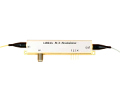
The R-AM Series LiNbO3 (lithium niobate) intensity modulators from Beijing Rofea Optoelectronics are designed for demanding high‑speed optical applications where signal fidelity, low drive voltage, and long‑term stability are essential. Based on a Mach–Zehnder (MZ) push‑pull structure and X‑cut LiNbO3 design, these integrated modulators deliver excellent electro‑optic performance, making them a strong choice for modern fiber‑optic communication links, laser sensing platforms, and radio‑over‑fiber (RoF) distribution systems. Similar to other high‑end LiNbO3 modulators used in advanced telecom and photonics labs, the R-AM family is engineered to provide consistent modulation characteristics over a wide optical wavelength and electrical bandwidth range.
Covering key telecom and specialty wavelengths, the R-AM series supports operation around 850 nm, 1060 nm, 1310 nm, and 1550 nm. This versatility allows system designers to integrate the same modulation architecture into short‑wavelength free‑space or sensing systems as well as long‑haul and metro fiber‑optic links. Typical 3 dB electrical bandwidths start at approximately 10 GHz for most wavelength options, with versions reaching up to 20 GHz and above for higher‑speed formats. At 850 nm, for example, the R‑AM‑08‑10G model offers a typical operating range from 830 nm to 870 nm with a 10–12 GHz electrical bandwidth, enabling high‑speed digital modulation as well as precise analog and sub‑carrier modulation schemes.
The series is optimized for low insertion loss and strong extinction performance. For most configurations, insertion loss is typically below 5 dB, while extinction ratios exceed 20 dB at DC, ensuring clean on/off modulation and high optical contrast. In practical high‑speed use, the dynamic extinction ratio remains suitable for advanced modulation formats and sideband generation. The combination of low optical loss and high extinction makes these modulators appropriate for systems where link budget and signal integrity are critical, such as quantum key distribution setups and coherent detection test beds often found in cutting‑edge photonics research and industry evaluation labs.
A key strength of the R-AM LiNbO3 modulators is their low half‑wave voltage (Vπ). Depending on wavelength and bandwidth option, the RF Vπ at 1 kHz is typically in the range of about 2.5 V to 6 V, with the 850 nm 10 GHz version offering around 2.5–3 V. This low drive requirement reduces the burden on RF driver electronics, minimizes overall system power consumption, and facilitates integration into compact, high‑density modules. Bias Vπ values are similarly optimized, simplifying bias control for maintaining the desired operating point (such as quadrature). For many applications, this translates into more stable operation and easier long‑term calibration compared to modulators with higher drive voltages.
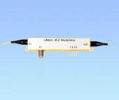
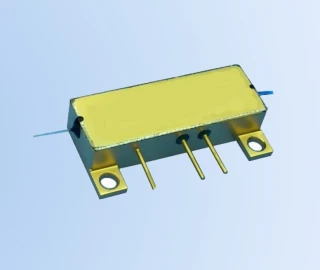
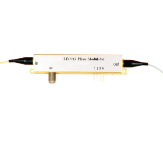
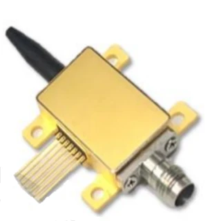
Fiber connectivity and mechanical design are tailored for practical deployment in both laboratory and industrial environments. The R‑AM‑08‑10G model, for instance, uses 850 nm polarization‑maintaining (PM) fiber at the input and output (125/250 μm), with standard FC/PC or FC/APC interfaces, and other connector options available on request. Similar flexibility is provided across the series, with combinations of PM–PM, PM–SMF, or fully customized fiber pigtails to match specific system architectures. The RF input is matched to 50 Ω and provided through an SMA female connector, while an independent bias port with high input impedance (on the order of 1 MΩ) allows fine control of the operating point using external bias controllers or driver boards.
From an electrical standpoint, the modulators are engineered to work seamlessly with typical RF signal chains used in photonics. Electrical return loss is specified to offer reliable impedance matching in the GHz regime, enabling stable broadband operation with minimal reflections when properly integrated into a 50 Ω environment. Maximum input optical power and RF power ratings are defined to protect the device against overload, and recommended bias voltage limits support safe operation in dynamic modulation scenarios. These characteristics position the R-AM family alongside other globally recognized LiNbO3 modulators that are widely used in coherent communication, microwave photonics, and precision measurement systems.
Environmental robustness is another important aspect of the R-AM design. Typical operating temperature ranges span from sub‑zero to elevated ambient temperatures, and the devices are qualified for extended storage temperature and humidity conditions. This makes the modulators suitable not only for benchtop R&D use, but also for deployment in field systems, production test setups, and industrial or telecom racks where temperature and humidity can vary over time.
Rofea LiNbO3 AM Series Intensity Modulator 850nm to 1550nm 20GHz
Specifications
| Aperture Diameter: | Not Specified |
|---|---|
| Peak Optical Power Density: | Not Specified |
| Wavelength Range: | 830 – 1550 nm |
| Transmission: | Not Specified |
| Extinction Ratio: | Not Specified |
| Model: | R-AM-08-10G |
| Type: | Intensity modulator |
| Operating Wavelength (range): | 830–870 nm |
| Operating Wavelength (center): | 850 nm |
| 3 DB Bandwidth (optical/electrical): | 10–12 GHz |
| Insertion Loss: | 4.5–5 dB |
| Optical Return Loss: | -45 dB |
| Switch Extinction Ratio @ DC: | 20 dB |
| Dynamic Extinction Ratio: | 13 dB |
| Input Fiber Type: | 850 nm PM fiber (125/250 μm) |
| Output Fiber Type: | 850 nm PM fiber (125/250 μm) |
| Optical Connector: | FC/PC, FC/APC or customization |
| Half-wave Voltage Vπ RF @ 1 KHz: | 2.5–3 V |
| Half-wave Voltage Vπ Bias @ 1 KHz: | 3–4 V |
| Electrical Return Loss S11: | -12 to -10 dB |
| RF Input Impedance ZRF: | 50 Ω |
| Bias Input Impedance ZBIAS: | 1 MΩ |
| Electrical Interface: | SMA (female) |
| Maximum Input Optical Power @ 850 Nm: | 10 dBm |
| Maximum Input RF Power: | 28 dBm |
| Bias Voltage Range: | -15 to +15 V |
| Operating Temperature Range: | -10 to +60 ℃ |
| Storage Temperature Range: | -40 to +85 ℃ |
| Humidity (non-condensing): | 5–90 %RH |
| Optical Input Port: | PM fiber (125 μm/250 μm) |
| Optical Output Port: | PM and SMF option |
| RF Port: | RF input port, SMA (female) |
| Bias Port: | Bias control port, pins 1–2 Bias, 3–4 N/C |
Got questions about specs? Use the inquiry form to ask.
 Download Data Sheet

Features
- Wide Wavelength Coverage – Supports multiple telecom and specialty bands, including 850 nm, 1064 nm, 1310 nm, and 1550 nm, suitable for data‑com, sensing, and RF-over-fiber links.
- High Modulation Bandwidth – Up to 10 GHz 3 dB bandwidth for 850/1064/1310/1550 nm versions and up to 20 GHz (and higher options like 28 GHz) at 1550 nm for advanced high‑speed modulation formats.
- Low Insertion Loss – Typical insertion loss < 5 dB, minimizing link budget penalty and preserving optical signal-to-noise ratio in long‑haul and short‑reach systems.
- High Extinction Ratio – DC extinction ratio up to > 23 dB (typical > 20 dB at 850 nm), enabling clean on/off keying, high dynamic range, and deep intensity modulation for demanding communication and sensing applications.
- Low Half-Wave Voltage (Vπ) – Low drive voltage with Vπ,RF as low as ~2.5–3 V at 1 kHz (850 nm type) and typically < 6 V across other wavelengths, reducing RF driver power requirements and system cost.
- MZ Push–Pull Design – Mach–Zehnder push–pull electrode structure on X‑cut LiNbO3 provides high linearity, improved modulation efficiency, and excellent chirp control compared to single‑arm designs.
- Stable LiNbO3 Platform – Built on X‑cut lithium niobate with proven electro‑optic performance, providing long‑term physical and chemical stability for both laboratory and industrial environments.
- Polarization-Maintaining Fiber Integration – Input and output ports with PM fiber (125/250 μm) for 850 nm and other bands ensure polarization stability and repeatable modulation performance; SMF output options available where required.
- Low Optical Return Loss – ORL typically < −45 dB reduces back‑reflections into lasers and upstream components, improving source stability and overall link performance.
- Good Electrical Matching – 50 Ω RF input with SMA(f) connector and well‑controlled S11 (≈ −10 to −12 dB) for efficient RF power transfer over multi‑GHz frequencies.
- Bias Port for DC Control – Dedicated bias input (high‑impedance, ~1 MΩ) enables precise operating point control (null, quadrature, or max) and compatibility with external automatic bias controllers.
- RF Power Handling – Supports RF input powers up to about +28 dBm (model‑dependent), suitable for strong modulation depth and wideband analog links such as RF-over-fiber.
- Compact and Robust Package – Integrated fiber pigtails and electrical ports in a compact housing with clear In / Out / RF / Bias labels, simplifying installation in optical benches, 19" racks, and OEM subsystems.
- Industrial-Grade Environmental Performance – Wide operating temperature range from −10 °C to +60 °C and storage from −40 °C to +85 °C with 5–90% RH humidity tolerance for reliable field deployment.
- Multiple Connector Options – Available with FC/PC, FC/APC and customized optical connector types to match existing fiber infrastructure and minimize back‑reflection in coherent or narrow‑linewidth laser systems.
- Optimized for Digital and Analog Modulation – Suitable for NRZ, PAM, and advanced modulation formats as well as high‑linearity analog modulation for CATV, microwave photonics, and test & measurement setups.
- Ideal for RF-over-Fiber Systems – High bandwidth, low Vπ, and good linearity make the R‑AM series a strong choice for RF-over-fiber (RoF), 5G fronthaul, satellite ground stations, and distributed antenna systems.
- Quantum & Sensing Ready – High extinction ratio and stable polarization handling support applications in quantum key distribution (QKD), lidar, interferometric sensing, and precision laser modulation.
- Sideband and Optical Carrier Suppression Modulation – Accurate phase and intensity control enable single-sideband (SSB) generation, optical carrier suppression, and frequency comb applications in advanced photonic systems.
- Flexible Customization Options – Customizable in terms of wavelength (850/1064/1310/1550 nm), bandwidth (300 MHz to 20+ GHz), fiber type (PM/SMF), connectors, and packaging to match specific OEM or research requirements.
Applications
- High‑speed fiber‑optic communication links – Use as an external LiNbO₃ Mach‑Zehnder intensity modulator for generating high‑fidelity on–off keyed (OOK), DPSK, and advanced modulation formats in 850 nm, 1064 nm, 1310 nm, and 1550 nm fiber‑optic links.
- Radio‑over‑fiber (RoF) and microwave photonics – Transport RF and microwave signals over optical fiber by intensity‑modulating the optical carrier with analog or digital RF signals up to 10–20 GHz, enabling low‑loss distribution of wireless, radar, CATV, and 5G/6G test signals.
- Quantum key distribution (QKD) transmitters – Implement high‑extinction‑ratio amplitude modulation for decoy‑state generation, pulse‑pattern encoding, and intensity control in 1310 nm and 1550 nm QKD systems and quantum communication testbeds.
- Lidar and laser ranging systems – Generate precisely shaped optical pulses (short, high‑contrast bursts) for time‑of‑flight lidar, 3D imaging, and long‑range distance measurement at 850 nm, 1064 nm, 1310 nm, and 1550 nm.
- Coherent optical transmission and test – Use as an external modulator in coherent transmitters for amplitude control, pilot tone insertion, and test signal generation in 100G/400G+ coherent communication systems.
- Optical arbitrary waveform generation – Combine with RF waveform generators to synthesize complex temporal optical intensity profiles for photonic signal processing and ultrafast optics research.
- Optical pulse carving and pulse picking – Carve short pulses from CW or mode‑locked lasers and perform pulse picking from high‑repetition‑rate pulse trains, enabling repetition‑rate reduction and timing control in ultrafast laser setups.
- Amplitude modulation for mode‑locked lasers – Stabilize or gate mode‑locked sources by high‑speed amplitude modulation, supporting laser synchronization, pump–probe experiments, and frequency‑comb manipulation.
- Sideband and subcarrier modulation – Realize controlled intensity modulation for optical double‑sideband (DSB), single‑sideband (SSB) with filtering, and subcarrier multiplexing schemes in advanced microwave‑photonic links.
- Analog optical links and CATV distribution – Implement linear, low‑distortion intensity modulation in analog fiber links used in cable television (CATV), antenna remoting, and instrumentation systems.
- Optical sensors and interferometric measurement – Use as a high‑speed, low‑drift amplitude modulator in fiber interferometers, optical gyros, and distributed sensing systems to control probe power, perform phase‑to‑intensity conversion, or implement lock‑in detection schemes.
- Laser sensing and spectroscopy – Perform intensity modulation for pump–probe spectroscopy, absorption spectroscopy, and photoacoustic excitation by modulating CW or pulsed lasers at RF/ GHz rates for high signal‑to‑noise detection.
- Secure optical links and optical encryption – Apply fast, programmable intensity patterns to optical carriers for physical‑layer encryption, secure key distribution, and spread‑spectrum optical communication.
- Test and measurement equipment – Integrate into optical test benches as a calibrated, broadband intensity modulator for characterizing photodetectors, receivers, amplifiers, and RF‑over‑fiber components up to 10–20 GHz.
- Optical clock distribution and timing systems – Modulate amplitude of timing pulses or CW carriers in precision timing and synchronization networks, including photonic clock distribution over fiber.
- Educational and research laboratories – Use as a versatile, easy‑to‑drive LiNbO₃ MZ modulator platform for demonstrations of electro‑optic effects, digital/analog modulation formats, interferometry, and high‑speed optical communication in universities and R&D labs.
- Optical packet and burst switching experiments – Perform fast on–off gating of data bursts and optical packets in experimental optical switching and data‑center interconnect architectures.
- Free‑space optical communication (FSO) – Generate intensity‑modulated optical carriers in 850 nm and 1550 nm free‑space links, enabling high‑speed, eye‑safe terrestrial or airborne communication channels.
- Photonic integration prototyping – Serve as an external benchmark modulator when developing or characterizing integrated photonic transmitters, providing a well‑known reference for performance comparison.
Frequently Asked Questions
What is the R-AM series LiNbO3 intensity modulator and what applications is it designed for?
What are the key optical and electrical specifications of the R-AM-08-10G 850 nm intensity modulator?
How do I correctly bias and drive the R-AM LiNbO3 intensity modulator for optimal performance?
How do I select the right R-AM intensity modulator configuration (wavelength, bandwidth, and fiber type) for my application?
What are the maximum input optical power, RF power, and environmental conditions for safe operation?
How do I interpret the extinction ratio (ER) and insertion loss specifications, and what do they mean for system performance?
What accessories or external circuits are recommended for using the R-AM series, and where can I find integration support?
Got more questions? Use the inquiry form to ask the supplier directly.
Similar Products



Your inquiry has been received.
Create an account by adding a password
Why create an account?
- Auto-complete inquiry forms
- View and manage all your past messages
- Save products to your favorites
- Close your account anytime — no hassle