
Description
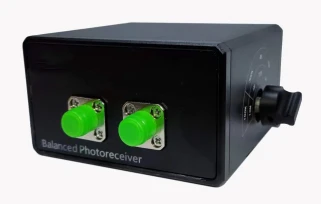
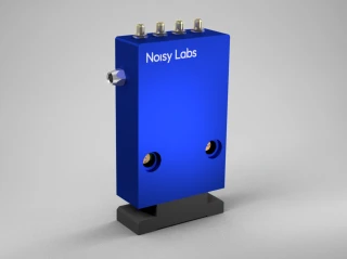
The ROF-GBPR-150M series is a high‑performance, gain‑adjustable balanced detection module designed for precise optical signal measurement over a wide frequency range from DC to 150 MHz. Engineered for demanding laboratory, industrial, and system-integration environments, this balanced detector offers five selectable gain levels, enabling users to optimize sensitivity, bandwidth, and dynamic range for a wide variety of optical test scenarios. With versions covering both 850–1650 nm (InGaAs, ROF-GBPR-150M-A-DC) and 400–1100 nm (Si, ROF-GBPR-150M-B-DC), the module is suitable for telecom wavelengths, fiber‑optic communications, laser diagnostics, and general photonics research.
In many precision photonic measurements, balanced detection is essential for suppressing common‑mode noise such as laser intensity fluctuations, environmental interference, and electronic pickup. The ROF-GBPR-150M series incorporates a matched PIN photodiode pair and a low‑noise transimpedance front end to deliver a common‑mode rejection ratio (CMRR) greater than 25 dB. This allows users to detect small differential signals buried under large common‑mode backgrounds, which is especially valuable in coherent communication experiments, interferometry, optical heterodyne/homodyne detection, and quantum optics setups. By offering a choice between InGaAs and Si detector types, the module aligns with typical operating wavelengths used in both telecom‑band and visible/near‑IR laser systems, enhancing flexibility across different platforms.
A key advantage of this series is its five‑step gain adjustment, providing conversion gains of 10³, 10⁴, 10⁵, 10⁶, and 10⁷ V/A. Each gain setting corresponds to a specific effective 3 dB bandwidth (DC–150, 45, 4, 0.3, and 0.1 MHz), giving users precise control over the trade‑off between sensitivity and speed. At lower gain settings, the detector supports high‑speed measurements up to 150 MHz for fast modulation, pulsed laser characterization, and high‑frequency signal analysis. At higher gain settings, it achieves improved sensitivity for low‑power or weakly modulated signals, making it suitable for applications such as lock‑in detection, low‑light spectroscopy, and precision metrology. Compared with many fixed‑gain balanced photoreceivers found in standard catalogs, this integrated, multi‑gain approach reduces the need for external amplification stages and simplifies system design.
The noise performance of the ROF-GBPR-150M series is carefully optimized across its operating bands, with typical output noise levels ranging from about 30 mVRMS in the lowest bandwidth setting down to around 3 mVRMS at the full 150 MHz range. This enables detection sensitivities down to approximately −60 dBm (InGaAs version) or −57 dBm (Si version) under DC–0.1 MHz operation, while still maintaining competitive sensitivity at higher bandwidth settings. At the upper end of the dynamic range, the module supports continuous‑wave saturated optical powers up to 0 dBm or 3 dBm depending on wavelength and bandwidth, with a maximum input optical power rating of 10 mW. This combination of low noise and wide linear range makes the detector well‑suited for experiments where both weak and relatively strong signals must be measured without reconfiguring the entire setup.
From a system‑integration perspective, the module is designed for straightforward deployment in optical testbeds and OEM instruments. It operates from a standard ±15 V DC supply with a working current under 100 mA, making it easy to power from typical laboratory supplies or system backplanes. The optical input is provided via an FC/APC connector, which minimizes back‑reflection and is compatible with common single‑mode fiber infrastructures. On the electrical side, the output is a 50 Ω SMA connector, ready to interface with oscilloscopes, RF spectrum analyzers, data acquisition cards, and lock‑in amplifiers. The default DC‑coupled output (with optional AC coupling) supports analysis of both slow and fast signal components, including low‑frequency drifts and modulation envelopes, which is often a limitation of AC‑only receivers available on the market.
Thermal and environmental robustness are also considered in the ROF-GBPR-150M series design. The module operates reliably over a temperature range of −20 to 70 °C and can be stored between −40 and 85 °C, making it suitable for both controlled laboratory environments and more demanding field or rack‑mounted installations.
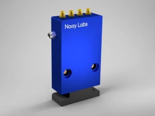
ROF GBPR 150MHz Gain Adjustable Balanced Photodetector Module FC SMA
Specifications
| Central Wavelength: | 850 – 1650 nm |
|---|---|
| Quantum Efficiency (typical): | Not Specified |
| Quantum Efficiency (max): | Not Specified |
| Active Area Size: | Not Specified |
| Angle Of Incidence (AOI): | Not Specified |
| Max Total Input Power: | 10 mW |
| 3dB Bandwidth: | 150 MHz |
| AC High Pass Cutoff: | Not Specified |
| Output Impedance: | Not Specified |
| Dark Noise Clearance (min): | Not Specified |
| DC Output Voltage: | -15 – 15 V |
| RF Input Frequency: | Not Specified |
| RF Input Power (max): | Not Specified |
| Product Series: | ROF-GBPR gain adjustable balanced detection module |
| Wavelength Response (standard): | 850–1650 nm |
| Wavelength Response (optional): | 400–1100 nm |
| Model ROF-GBPR-150M-A-DC Spectral Response Range: | 850–1650 nm |
| Model ROF-GBPR-150M-B-DC Spectral Response Range: | 400–1100 nm |
| Detector Type (A-DC): | InGaAs/PIN |
| Detector Type (B-DC): | Si/PIN |
| Responsivity (A-DC): | ≥0.95 A/W @ 1550 nm |
| Responsivity (B-DC): | ≥0.5 A/W @ 850 nm |
| 3 DB Bandwidth (all Gain Gears): | DC–150, 45, 4, 0.3, 0.1 MHz |
| Common Mode Rejection Ratio: | >25 dB |
| Gain Adjustable: | 5 gain gears |
| Conversion Gain (high Resistance State): | 10^3, 10^4, 10^5, 10^6, 10^7 V/A |
| Noise Voltage (DC–0.1 MHz): | 30 mVRMS |
| Noise Voltage (DC–0.3 MHz): | 12 mVRMS |
| Noise Voltage (DC–4.0 MHz): | 10 mVRMS |
| Noise Voltage (DC–45 MHz): | 6 mVRMS |
| Noise Voltage (DC–150 MHz): | 3 mVRMS |
| Sensitivity (A-DC, DC–0.1 MHz): | -60 dBm |
| Sensitivity (A-DC, DC–0.3 MHz): | -47 dBm |
| Sensitivity (A-DC, DC–4.0 MHz): | -40 dBm |
| Sensitivity (A-DC, DC–45 MHz): | -30 dBm |
| Sensitivity (A-DC, DC–150 MHz): | -23 dBm |
| Sensitivity (B-DC, DC–0.1 MHz): | -57 dBm |
| Sensitivity (B-DC, DC–0.3 MHz): | -44 dBm |
| Sensitivity (B-DC, DC–4.0 MHz): | -37 dBm |
| Sensitivity (B-DC, DC–45 MHz): | -27 dBm |
| Sensitivity (B-DC, DC–150 MHz): | -20 dBm |
| Saturated Optical Power (A-DC, DC–0.1 MHz): | -33 dBm |
| Saturated Optical Power (A-DC, DC–0.3 MHz): | -23 dBm |
| Saturated Optical Power (A-DC, DC–4.0 MHz): | -13 dBm |
| Saturated Optical Power (A-DC, DC–45 MHz): | -3 dBm |
| Saturated Optical Power (A-DC, DC–150 MHz): | 0 dBm |
| Saturated Optical Power (B-DC, DC–0.1 MHz): | -30 dBm |
| Saturated Optical Power (B-DC, DC–0.3 MHz): | -20 dBm |
| Saturated Optical Power (B-DC, DC–4.0 MHz): | -10 dBm |
| Saturated Optical Power (B-DC, DC–45 MHz): | 0 dBm |
| Saturated Optical Power (B-DC, DC–150 MHz): | 3 dBm |
| Operating Voltage: | DC ±15 V |
| Working Current: | <100 mA |
| Maximum Input Optical Power: | 10 mW |
| Output Impedance: | 50 Ω |
| Operating Temperature: | -20–70 ℃ |
| Storage Temperature: | -40–85 ℃ |
| Output Coupling Mode (default): | DC coupling |
| Output Coupling Mode (optional): | AC coupling |
| Input Optical Connector: | FC/APC |
| Electrical Output Interface: | SMA |
| Supported Bandwidth Options (family): | 10M, 80M, 200M, 350M, 400M, 1G, 1.6G, 150M |
| Operating Wavelength Code A: | 850–1650 nm (1550 nm test) |
| Operating Wavelength Code B: | 320–1000 nm (850 nm test) |
| Operating Wavelength Code A1: | 900–1400 nm (1064 nm test) |
| Operating Wavelength Code A2: | 1200–1700 nm (1310 nm or 1550 nm test) |
Got questions about specs? Use the inquiry form to ask.
 Download Data Sheet

Features
- Wide Wavelength Coverage – Supports 850–1650 nm as standard for InGaAs/PIN (telecom bands including 1310 nm & 1550 nm) and optional 400–1100 nm Si/PIN version for VIS–NIR applications, covering most fiber‑optic and free‑space optical test scenarios.
- DC to 150 MHz Bandwidth with Selectable Settings – Five selectable bandwidth/gain gears from DC–0.1 MHz up to DC–150 MHz, enabling optimization for low‑frequency, narrowband, or broadband measurements in one compact module.
- Five‑Step Gain Adjustment – Programmable transimpedance gain of 10³, 10⁴, 10⁵, 10⁶, 10⁷ V/A allows precise optimization of sensitivity and dynamic range for weak, medium, or strong optical signals.
- Balanced Detection Architecture – Integrated balanced (differential) detector design provides improved noise performance and common‑mode noise suppression, ideal for coherent detection, interferometry, and intensity noise cancellation.
- High Common‑Mode Rejection Ratio (CMRR) – CMRR of > 25 dB effectively suppresses common‑mode intensity and environmental noise, enhancing SNR compared with single‑ended detectors used in similar frequency ranges.
- Low Noise Performance – Optimized low‑noise amplification with typical output noise as low as 3 mV RMS at DC–150 MHz, improving detection of small optical power fluctuations in demanding lab and production test environments.
- High Optical Sensitivity – Detects very low CW optical powers, with sensitivity down to approximately −60 dBm (DC–0.1 MHz) for the 850–1650 nm version and −57 dBm for the 400–1100 nm version, suitable for weak‑signal measurements and precision metrology.
- Wide Linear Dynamic Range & Saturation Handling – Saturated optical power up to 0 dBm to +3 dBm at the highest bandwidth gear, combined with a maximum safe input power of 10 mW, provides a broad dynamic range for both low‑level and higher‑power signals.
- Flexible Coupling Options – Standard configuration uses DC coupling on the RF output for low‑frequency and DC measurements, with AC coupling available on request to match high‑frequency test setups and protect downstream instruments.
- Industry‑Standard Optical & Electrical Interfaces – Equipped with FC/APC fiber input to minimize back‑reflection in fiber systems and a 50 Ω SMA electrical output, ensuring easy integration with RF instruments, oscilloscopes, analyzers, and OEM boards.
- Multiple Spectral Response Options Across the Series – The ROF‑GBPR/ROF‑BPR family supports additional bands such as 320–1000 nm (B), 900–1400 nm (A1), and 1200–1700 nm (A2), making it a scalable platform for different wavelengths and bandwidths up to 1.6 GHz.
- Stable ±15 V Supply Operation – Operates from a standard ±15 V DC power input with < 100 mA current consumption, compatible with common laboratory and OEM power rails.
- Robust Environmental Specifications – Wide operating temperature range of −20 to +70 °C and storage range of −40 to +85 °C, supporting both laboratory use and more demanding industrial or field environments.
- Compact, Professional Module Design – Purpose‑built, shielded module provides mechanical robustness and EMI reduction, facilitating clean integration into optical test benches, coherent receivers, and system‑level optical front‑ends.
- Ideal for Advanced Optical Measurement Applications – Suited for optical communication testing, coherent detection, optical heterodyne/homodyne systems, laser RIN and intensity noise measurements, interferometric sensing, and high‑precision metrology where adjustable gain and balanced detection are critical.
Applications
- High‑speed coherent optical communication systems
Ideal as a gain‑adjustable balanced detector for coherent receivers, intradyne and heterodyne detection, and advanced modulation formats (QPSK, QAM) in metro, long‑haul, and data‑center interconnect links. - Optical heterodyne and homodyne detection
Used to mix a local oscillator (LO) with weak signal light for phase‑sensitive detection in laboratory and industrial coherent detection setups from DC up to 150 MHz. - Laser phase and frequency noise measurement
Balanced configuration and high CMRR (>25 dB) enable precise characterization of laser phase/frequency noise, linewidth, and relative intensity noise (RIN) for telecom, sensing, and metrology lasers. - Quantum optics and quantum communication experiments
Suitable for balanced homodyne detection of squeezed states, entangled photons, and weak quantum signals in free‑space or fiber‑based quantum key distribution (QKD) and quantum information research. - Optical time‑domain and frequency‑domain reflectometry
Enhances sensitivity in coherent OTDR/OFDR setups for distributed fiber sensing, fault location, and component characterization over telecom wavelengths (InGaAs) or visible/near‑IR (Si). - High‑precision interferometry and metrology
Supports Mach‑Zehnder, Michelson, and Sagnac interferometers where common‑mode noise rejection and adjustable gain are critical for measuring tiny phase or path‑length variations. - Optical coherence tomography (OCT) and biomedical imaging
Applicable as a balanced detection front‑end in time‑domain and swept‑source OCT systems to improve SNR, reduce excess noise, and enable higher‑contrast imaging in medical and biological research. - Laser stabilization feedback loops
Provides low‑noise error signals for active laser frequency, phase, and intensity stabilization in cavity locking, Pound–Drever–Hall (PDH) locking, and servo control systems. - Precision spectroscopy and metrology
Used in coherent and heterodyne spectroscopy, frequency comb detection, and high‑resolution absorption/dispersion measurements where DC–150 MHz bandwidth and tunable gain are required. - Fiber‑optic sensor interrogation
Improves performance of interferometric fiber sensors (FBG arrays, Fabry‑Perot, Sagnac, and distributed acoustic/vibration sensors) by rejecting common‑mode noise and optimizing gain to the signal level. - Optical RIN and low‑frequency noise characterization
DC‑coupled operation allows accurate measurement of laser intensity noise and low‑frequency fluctuation analysis across multiple gain/bandwidth settings. - Optical communication transceiver development and testing
Serves as a flexible balanced front‑end for evaluating new modulation formats, advanced DSP algorithms, and integrated photonic transmitters/receivers in R&D environments. - Free‑space optical (FSO) links and atmospheric channel research
Si and InGaAs balanced detection options support experimental FSO and visible/IR communication links requiring high sensitivity and mitigation of atmospheric intensity noise. - Optical gyro and inertial sensing systems
Used in interferometric fiber‑optic gyroscopes (FOGs) and related inertial sensors where balanced readout improves detection of rotation‑induced phase shifts and minimizes drift. - Ultrafast and mode‑locked laser diagnostics
Enables balanced RF detection of pulse trains, amplitude noise, and beat notes from mode‑locked and comb lasers in the DC–150 MHz range for timing and stability analysis. - Optical component and subsystem characterization
Suitable for testing modulators, attenuators, filters, splitters, integrated photonics chips, and other passive/active devices under balanced detection to measure insertion loss, phase, and intensity noise. - Laboratory teaching and advanced photonics training
Balanced detector module is convenient for university and training labs to demonstrate coherent detection, homodyne/heterodyne techniques, interferometry, and noise suppression concepts. - Low‑light and weak‑signal detection in R&D
High conversion gain (up to 107 V/A), selectable bandwidth, and low noise voltage make the module ideal for detecting very weak optical signals in physics, chemistry, and engineering experiments.
Frequently Asked Questions
What is the ROF-GBPR Series gain adjustable balanced detection module and what are its main applications?
What wavelength ranges and detector types are available for the ROF-GBPR-150M balanced detector?
How does the gain adjustment work and what bandwidths are available for each gain setting?
What is the common‑mode rejection ratio (CMRR) and why is it important in a balanced detector?
What are the key electrical and optical performance specifications (bandwidth, noise, sensitivity, and saturation power)?
How do I power and connect the ROF-GBPR balanced detector in my setup?
How do I choose the correct ROF-BPR/ROF-GBPR model (bandwidth, wavelength band, coupling, and gain type)?
Got more questions? Use the inquiry form to ask the supplier directly.
Similar Products
Your inquiry has been received.
Create an account by adding a password
Why create an account?
- Auto-complete inquiry forms
- View and manage all your past messages
- Save products to your favorites
- Close your account anytime — no hassle