


Description
The 1550 nm Faraday Mirror from DK Photonics is a precision passive component engineered to control and stabilize polarization in single‑mode fiber optic systems. Designed around a high‑performance Faraday rotator element, this device provides a well‑defined 45‑ or 90‑degree rotation of the input light’s polarization state upon reflection. By reflecting the signal with a controlled polarization rotation, the Faraday Mirror effectively compensates for random polarization changes and birefringence in the optical path, helping to eliminate polarization‑induced fluctuations that can degrade system performance.
In modern fiber infrastructures operating around the C‑band, polarization sensitivity can directly affect signal quality, noise figure, and long‑term stability. The DK Photonics 1550 nm Faraday Mirror addresses these challenges by combining high isolation, low insertion loss, and high return loss in a compact, robust package. Its epoxy‑free optical path minimizes outgassing and thermal stress, ensuring stable performance over a wide operating temperature range. This makes the device particularly suitable for demanding laboratory environments, long‑haul telecom links, and high‑power or narrow‑linewidth laser architectures where polarization control is critical.
Typical applications include fiber interferometers, Brillouin and Raman amplifier systems, fiber laser cavities, coherent detection setups, and fiber optic antenna remoting. In interferometric systems, the Faraday Mirror is used at the end of a fiber arm to automatically compensate for random polarization changes along the fiber, significantly improving fringe visibility and measurement repeatability. In amplifier and laser configurations, it helps maintain a stable polarization state, thus enhancing gain uniformity, suppressing noise, and improving overall system reliability. It is also highly effective in fiber‑optic test and measurement environments, where precise control of reflected polarization can simplify setups and enable more accurate characterization of components and subsystems.
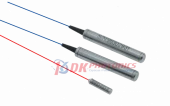
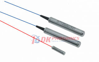
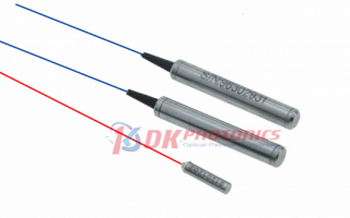
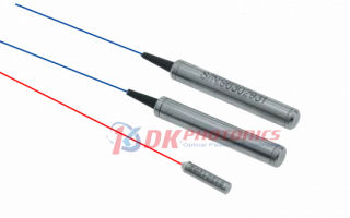
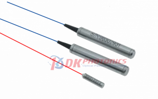
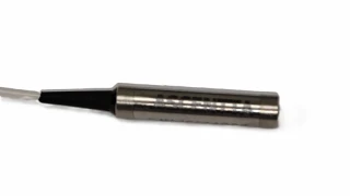
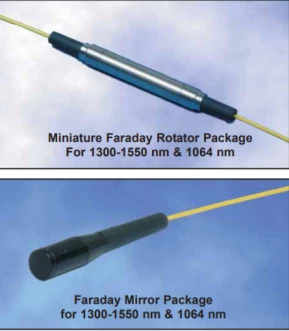
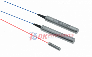
The 1550 nm Faraday Mirror is available with standard center wavelength at 1550 nm and can be tailored for custom wavelengths on request to match specialized system requirements. DK Photonics offers both 45° and 90° Faraday rotation angles, allowing engineers to select the configuration that best aligns with their optical design, especially in polarization diversity and polarization‑maintaining applications. The device is supplied in compact cylindrical packages, such as Ø5.5 mm × L35 mm or Ø3.0 mm × L12 mm, supporting easy integration into space‑constrained modules, fiber trays, or benchtop assemblies.
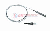
For seamless deployment, users can choose among different fiber pigtail options and lengths. Standard versions are offered with 250 µm bare fiber pigtails or 0.9 mm loose‑tube fiber, while other diameters and jacketing can be provided for ruggedized or specialty environments. Typical pigtail lengths are 0.5 m, 1.0 m, or 1.5 m, but custom lengths are available to match the exact layout of an instrument or rack‑mounted subsystem. The device can be supplied without connectors for direct fusion splicing, or with popular connector types such as FC/PC, FC/APC, SC/APC, LC/APC, or application‑specific interfaces, supporting straightforward integration into existing fiber networks or test benches.
By combining a stable Faraday rotator design with an epoxy‑free optical path, the DK Photonics 1550 nm Faraday Mirror delivers low insertion loss, high return loss, and excellent environmental stability. This makes it a versatile choice for fiber optic LAN systems, telecommunications nodes, DWDM/EDFA platforms, and precision measurement instruments where polarization control must be reliable over time and under varying operating conditions. Whether you are optimizing an interferometer, stabilizing a fiber laser cavity, or improving the repeatability of fiber‑optic testing setups, this Faraday Mirror provides a compact, high‑performance solution that enhances polarization robustness and overall system stability.
1550nm Faraday Mirror
Specifications
| Center Wavelength: | 1550 nm |
|---|---|
| Operating Bandwidth: | 30 nm |
| Insertion Loss (max): | 0.6 dB |
| Faraday Rotation Angle (single Pass): | 45 deg deg |
| Faraday Rotation Angle: | 45° |
| Dimensions: | Ø5.5mmxL35mm |
| Pigtails Diameter: | 900μm Loose Fiber |
| Fiber Length: | 1.0m |
| Connector: | None |
Got questions about specs? Use the inquiry form to ask.
 Download Data Sheet

Features
- Optimized for 1550 nm Operation
Engineered specifically for the 1550 nm telecom window, ensuring minimal loss and stable performance in long‑haul, metro, and access fiber networks. - High Polarization Rotation Accuracy (45° or 90°)
Provides precise 45° or 90° Faraday rotation of the polarization state, enabling accurate polarization control and compensation in interferometers, sensing, and laser systems. - High Isolation & Polarization Insensitivity
Faraday mirror design inherently cancels polarization effects on round‑trip propagation, eliminating polarization‑induced fading and improving system stability in interferometric and coherent setups. - Low Insertion Loss
Optimized optical design and high‑quality coatings deliver very low insertion loss, maximizing signal power and system OSNR in EDFAs, Raman amplifiers, and measurement systems. - High Return Loss / Reflectivity
Provides high return loss with excellent reflectivity, reducing back‑reflection into upstream components and improving the performance of lasers, amplifiers, and test setups. - Epoxy‑Free Optical Path
All‑glass, epoxy‑free optical path in the signal region eliminates aging and outgassing issues, delivering superior reliability, low drift, and excellent long‑term stability over temperature and power. - Compact, Rugged Package Options
Available in Ø5.5 × 35 mm and Ø3.0 × 12 mm packages, supporting easy integration into dense modules, fiber sensors, and OEM platforms where space is at a premium. - Flexible Fiber and Pigtail Configurations
Supports 250 μm bare fiber or 0.9 mm loose tube pigtails and customizable fiber lengths (e.g., 0.5 m, 1.0 m, 1.5 m), enabling convenient routing and integration into existing fiber infrastructure. - Connector Options or Bare Fiber
Offered with standard connectors such as FC/PC, FC/APC, SC/APC, LC/APC or with no connector, providing maximum flexibility for splicing, field termination, and lab use. - Designed for Fiber Amplifier and Laser Systems
Ideal for fiber amplifiers, Brillouin/EDF/raman systems, and fiber lasers, where stable polarization behavior, low loss, and high return loss are critical to achieving consistent output power and linewidth. - Enhanced Performance in Interferometric and Sensing Applications
Widely used in fiber interferometers, fiber optic gyros, distributed sensing (DAS/DTSS), and OCT‑type setups to reduce polarization‑induced fluctuations and improve measurement repeatability. - Telecom‑Grade Reliability
Built for telecommunications and fiber LAN systems, meeting stringent stability and reliability demands under real‑world environmental conditions. - Easy Integration into Test & Measurement Setups
Suitable for fiber optic system testing and characterization, providing a stable, known polarization‑rotating reflection point for calibration, polarization scrambling, and component evaluation. - Custom Wavelengths and Specifications Available
In addition to the 1550 nm standard version, custom center wavelengths, rotation angles, pigtail types, lengths, and packages can be tailored to specific OEM or research requirements. - Consistent Performance Across Temperature
Epoxy‑free design and robust mechanical packaging deliver excellent thermal stability, making the device suitable for demanding environments and outdoor or field‑deployed systems.
Applications
- Polarization-Insensitive Fiber Interferometers – Use Faraday mirrors to eliminate polarization-induced fading and fluctuations in Mach–Zehnder, Michelson, and Sagnac interferometers for high-stability sensing and metrology setups.
- Fiber Optic Gyroscopes (FOG) – Improve bias stability and reduce polarization-related errors in interferometric fiber optic gyroscopes used in navigation and inertial measurement systems.
- Fiber Laser Systems – Implement in linear-cavity and ring-cavity fiber lasers to compensate polarization changes in the cavity, stabilize output power, and enhance beam quality in single-frequency, pulsed, or CW fiber lasers.
- Brillouin / Raman Fiber Amplifier Systems – Mitigate polarization dependence in Brillouin and Raman amplifiers, enabling more stable gain and reduced polarization noise in long-haul and specialty amplification schemes.
- Erbium-Doped Fiber Amplifiers (EDFA) – Integrate in EDFA designs to reduce polarization-dependent gain and improve overall amplifier stability in C-band (around 1550 nm) optical communication links.
- Telecommunications and DWDM Networks – Use in high-speed telecom systems, WDM/DWDM links, and coherent communication setups to compensate polarization effects in return paths and reflection-based components.
- Fiber Optic LAN and Access Networks – Apply in metro, FTTx, and enterprise fiber networks where polarization-insensitive operation of reflective or bidirectional components is required.
- Polarization-Diverse Coherent Receivers – Employ Faraday mirrors in coherent detection schemes and homodyne/heterodyne receivers to help manage polarization states in reference and signal arms.
- Optical Time-Domain Reflectometry (OTDR) and Network Testing – Use as a reference termination in OTDR, backscatter, and reflectometry measurements to create stable, known reflection points independent of polarization.
- Fiber Optic Component Characterization – Integrate in test benches for circulators, couplers, isolators, filters, and modulators to suppress polarization sensitivity and obtain more repeatable IL/RL measurements.
- Distributed Fiber Sensing (DAS, DTS, DVS) – Improve performance in distributed acoustic, temperature, and vibration sensing systems that rely on interferometric or backscattering measurements in long fiber runs.
- Optical Coherence Tomography (OCT) & Biomedical Optics – Use in OCT interferometers and biomedical fiber probes to reduce polarization artifacts and improve image stability and signal uniformity.
- Fiber Optic Antenna Remoting and RF-over-Fiber – Incorporate in antenna remoting links (e.g., radar, satellite, and telecom RF-over-fiber) to stabilize polarization in reflection-based or bidirectional modules.
- Remote Interferometric Sensing and Monitoring – Apply in environmental, structural-health, and geophysical monitoring systems using interferometric fiber sensors to minimize polarization-related signal drift.
- Quantum Communication and Quantum Optics Experiments – Use as polarization-rotating reflectors in quantum key distribution (QKD) setups and entangled-photon interferometers to help manage polarization states over long fibers.
- Polarization Mode Dispersion (PMD) and PDL Compensation Schemes – Integrate in experimental and specialty links aimed at reducing effective PMD/PDL via polarization scrambling and reciprocal propagation paths.
- Bidirectional Test Loops and Loop-Back Modules – Use Faraday mirrors as compact loop-back terminations to create polarization-insensitive bidirectional test paths in laboratories and production testing.
- Reflective Fiber Sensors – Employ in fiber Bragg grating (FBG) and other reflective sensor configurations to compensate for polarization changes in the sensing fiber and improve measurement repeatability.
- Laser Cavity Mirrors for Specialty Wavelengths – Utilize at or around 1550 nm (and custom wavelengths) as in-cavity Faraday rotating mirrors for specialty laser wavelengths where polarization stability is critical.
- General Polarization Control in Fiber Systems – Use wherever a stable 45° or 90° polarization rotation upon reflection is needed to turn non-reciprocal, polarization-sensitive paths into effective polarization-insensitive links.
Frequently Asked Questions
What is a 1550 nm Faraday Mirror and how does it work?
What are the main applications of the DK Photonics 1550 nm Faraday Mirror?
What are the key performance advantages of this Faraday Mirror compared to standard fiber reflectors?
How do I choose between a 45° and 90° Faraday rotation angle for my application?
How do I correctly specify and order a DK Photonics 1550 nm Faraday Mirror?
What fiber pigtail and connector options are available, and how do they affect performance?
What should I consider when integrating a 1550 nm Faraday Mirror into my fiber‑optic system?
Got more questions? Use the inquiry form to ask the supplier directly.
Similar Products
Your inquiry has been received.
Create an account by adding a password
Why create an account?
- Auto-complete inquiry forms
- View and manage all your past messages
- Save products to your favorites
- Close your account anytime — no hassle