


Description
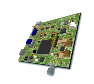
The MBC-HER Modulator Bias Controller is a compact, PCB‑level controller engineered for precise bias stabilization of single Mach–Zehnder (MZ) modulators in high‑extinction‑ratio optical systems. It is optimized for demanding analog and digital photonic applications where stable operation at quadrature, null, or peak is critical to system performance. Designed as a stand‑alone module with no computer interface required, it integrates easily into OEM platforms, testbeds, and field‑deployed equipment that must maintain low distortion and high extinction over time, temperature, and input power variations.
In operation, the controller continuously monitors the modulator output intensity via an internal or external photodetector and adjusts the modulator bias voltage from –13.5 V to +13.5 V to hold the chosen operating point. The MBC-HER supports locking to positive‑slope quadrature (Quad+), negative‑slope quadrature (Quad‑), null, or peak on the MZ transfer curve. These modes, along with the locking slope and priority (0 V or 8 V), are user‑selectable via on‑board jumpers. This flexibility makes the unit well suited to a wide range of coherent communication links, intensity‑modulated analog links, RF‑over‑fiber systems, and laboratory setups where the optimum bias point may differ between experiments or product lines.
A key differentiator of the MBC-HER compared with many generic bias controllers is its very low pilot tone modulation depth. In quadrature operation the pilot tone typically remains in the 1–2% range, which helps preserve signal integrity and enables exceptionally high extinction ratios, typically above 30 dB and reaching beyond 45 dB when used with high‑performance MZ modulators. In null mode, the device supports extinction ratios up to approximately 53 dB, making it suitable for applications that demand deep carrier suppression or highly efficient on/off keying. The low‑level pilot tone is carefully chosen in frequency (approximately 1 kHz in Quad mode and 2 kHz in Null mode) to simplify filtering and minimize interference with the user signal band.
The controller operates over a broad optical wavelength range from 1000 nm to 1650 nm, allowing one unit to support systems spanning the O‑, E‑, S‑, C‑, and L‑bands. This wavelength‑agnostic design ensures compatibility with many lithium‑niobate and other MZ modulators commonly used in fiber‑optic links. The detector input power range is tailored for reliable feedback control in both quadrature and null/peak modes, typically accommodating –30 to –10 dBm in peak/null operation and –20 to –10 dBm in quadrature mode. This provides sufficient headroom for integration with standard 1–5% tap couplers placed after the modulator, as is typical in bias control architectures used in RF‑over‑fiber and digital transport systems.
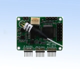
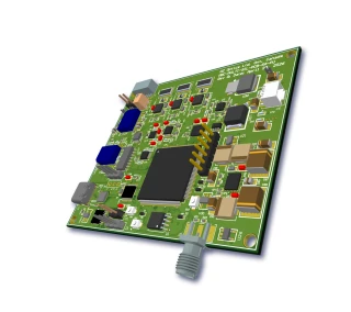
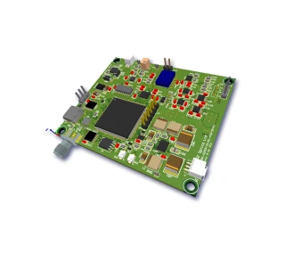
From a hardware integration perspective, the MBC-HER is delivered as a miniature PCB module with approximate dimensions of 1.6 × 3.05 × 0.65 inches. Multiple mounting holes are provided for easy attachment within instrument chassis, rack‑mounted platforms, or custom enclosures. The unit requires symmetrical ±15 V supplies (with typical currents of about 60 mA on the positive rail and 40 mA on the negative rail), making it compatible with standard laboratory and telecom‑grade power systems. The operating temperature range from 0 °C to 70 °C and storage range from –40 °C to 85 °C are suitable for controlled environments such as telecom central offices, network laboratories, and sheltered outdoor nodes.
For optical feedback, the MBC-HER can be ordered with an integrated pigtailed photodiode or configured to use an external photodetector. This flexibility allows designers to optimize the monitoring tap location and detector characteristics to match specific link budgets and modulation formats. Standard telecommunication connector options are supported, including FC/UPC, FC/APC, SC/UPC, SC/APC, LC/UPC, and LC/APC, simplifying fiber management and integration with existing infrastructure. When used together with a continuous‑wave laser, an MZ modulator, a 1–5% coupler, and a photodiode, the controller forms a complete bias stabilization loop that maintains optimum modulator operating conditions with minimal user intervention.
The MBC-HER is particularly suitable for system designers and researchers who require a robust, high‑extinction ratio bias control solution without the complexity of software control or bulky instrumentation. Calibration and locking modes, along with a dedicated calibration‑off function, enable quick setup, fast recovery after power cycling, and straightforward optimization during development.
MBC-HER High Extinction Ratio Mini Modulator Bias Controller
Specifications
| Product Type: | MBC-MINI |
|---|---|
| Modulation Type: | Other |
| Detector Input Power: | -20 dBm |
| Locking Slope: | Unspecified |
| Locking Mode: | Quad+, Quad-, Null, Peak Positions |
| Photodetector Type: | Unspecified |
| Tunability: | Unspecified |
| Product Name: | MBC-HER Modulator Bias Controller - High Extinction Ratio Mini |
| Part Number: | MBC-HER-PP-X-LV |
| Pigtailed Photodiode Option: | PD = included; 00 = not included |
| Connector Code Options: | 3U = FC/UPC; 3A = FC/APC; SCU = SC/UPC; SCA = SC/APC; LCU = LC/UPC; LCA = LC/APC |
| Bias Lock Priority Options: | LV = 0 (0 V priority) or 8 (8 V priority) |
| Detector Input Power (Peak/Null Mode): | -30 to -10 dBm |
| Detector Input Power Range (Quad Mode): | -20 to -10 dBm |
| Optical Wavelength Range: | 1000–1650 nm |
| Bias Voltage Range: | -13.5 to +13.5 V |
| Null Mode Extinction Ratio: | 30 to 53 dB |
| Bias Locking Priority: | 0 V or 8 V |
| Locking Slope: | Positive or Negative |
| Locking Mode: | Quad+ (Quad-) or Null (Peak) |
| Pilot Tone Modulation Depth (QUAD): | 1–2 % |
| Pilot Tone Vpp (Null): | 6 mV |
| Pilot Tone Frequency (QUAD): | 1000 Hz |
| Pilot Tone Frequency (NULL): | 2000 Hz |
| Positive Power Voltage: | 14.5 to 15.5 V (typ. 15 V) |
| Negative Power Voltage: | -14.5 to -15.5 V (typ. -15 V) |
| Positive Power Current: | 60 mA |
| Negative Power Current: | 40 mA |
| Operating Temperature: | 0 to 70 °C |
| Storage Temperature: | -40 to 85 °C |
| Dimensions: | 1.6 x 3.05 x 0.65 inch |
| Board Length: | 3.050 in (77.47 mm) |
| Board Width: | 1.600 in (40.64 mm) |
| Mounting Hole Diameter: | 0.110 in (2.79 mm) |
| High Extinction Ratio Capability: | > 45 dB (application dependent) |
Got questions about specs? Use the inquiry form to ask.
 Download Data Sheet

Features
- Optimized for High-Extinction Ratio Modulation (> 45 dB possible)
Engineered for demanding high‑extinction ratio applications such as advanced optical communications, coherent systems, and high-dynamic-range test setups, with typical null-mode extinction ratios up to 53 dB (limited by modulator performance). - Full-Function Bias Control for Single MZ Modulators
Designed specifically for driving a single Mach‑Zehnder (MZ) modulator, maintaining a stable operating point across the full transfer curve for consistent, low‑distortion intensity modulation. - Multiple Locking Modes: Quad, Null, and Peak
Supports bias locking at Quad+, Quad‑, Null, and Peak working points, allowing precise selection of operating regime for linear modulation, on/off keying, or specialized signal formats. - User-Selectable Locking Slope and Mode via Jumpers
Flexible jumper-selectable operation lets the user choose positive or negative locking slope and switch between Quad+/Quad‑ and Null/Peak modes without external software or programming. - Ultra-Low Pilot Tone for Minimal Signal Degradation
Employs an extremely small pilot tone (1–2% modulation depth in QUAD mode, only a few mV in NULL mode) to detect and maintain the bias point, enabling very high extinction ratios while minimizing impact on the main data signal. - Dual Operating Modes: Calibration and Locking
Provides a Calibration Mode for initial setup and bias optimization, and a Locking Mode for long-term automatic stabilization, improving repeatability and simplifying system commissioning. - Fast System Setup with Calibration-Off Function
A dedicated calibration off function supports rapid system alignment and configuration before engaging the closed-loop locking, saving integration and bring-up time. - Selectable Bias Locking Priority (0 V or 8 V)
Allows the user to set a preferred bias locking priority (0 V or 8 V) during startup or recovery, helping to avoid lock-in to undesired operating points in complex or drifting systems. - Direct Photodetector Integration (Internal or External)
Includes an optional pigtailed photodiode for straightforward OEM integration, while also providing access for an external photodetector to support custom optical taps, couplers (e.g., 1–5% couplers), or existing monitor ports. - Wide Optical Wavelength Coverage (1000–1650 nm)
Compatible with a broad range of telecom and specialty wavelengths, including O-, C-, and L‑band operation, making it suitable for fiber‑optic communication, sensing, and research systems. - Broad Bias Voltage Range for Diverse Modulators
Provides a bias control range of -13.5 V to +13.5 V, supporting many commercial LiNbO₃ and other electro‑optic modulators with different half‑wave voltages and transfer functions. - No Computer Interface Required – True Standalone Operation
Fully hardware‑controlled module with on‑board electronics; does not require a PC, firmware configuration, or digital control, which simplifies deployment in OEM and field systems. - PCB-Level, Miniature OEM Form Factor
Compact footprint of approximately 1.6 x 3.05 x 0.65 inches (40.64 x 77.47 x 16.5 mm) with mounting holes, ideal for integration into space‑constrained instruments, line cards, or benchtop enclosures. - Robust Dual-Supply Powering
Operates from standard ±15 V supplies (typ. +15 V, -15 V) with low current consumption (approx. 60 mA positive, 40 mA negative), compatible with common laboratory and OEM power architectures. - Stable Performance Over Wide Temperature Range
Specified for 0 to +70 °C operating temperature and -40 to +85 °C storage temperature, ensuring reliable bias control in controlled labs as well as more demanding industrial environments. - Optimized Pilot Tone Frequencies for Accurate Locking
Distinct pilot tone frequencies for QUAD and NULL modes (around 1 kHz and 2 kHz, respectively) enhance detection accuracy and stability, while keeping interference with low‑frequency system components minimal. - Compatible with Standard Fiber Connector Options
Available with a range of common connector types (e.g., FC/UPC, FC/APC, SC/UPC, SC/APC, LC/UPC, LC/APC) for the pigtailed photodiode, simplifying connection to tap couplers and existing fiber infrastructures.
Applications
- High‑Extinction Coherent Optical Communication Links – Maintain stable bias on LiNbO₃ Mach‑Zehnder (MZ) modulators in coherent DP‑QPSK, QAM, and advanced modulation format transmitters to achieve extinction ratios >45 dB and minimize signal degradation in DWDM systems.
- High Dynamic Range Analog Fiber‑Optic Links (RF‑over‑Fiber) – Stabilize the operating point of MZ modulators in analog microwave, CATV, and satellite RF‑over‑fiber links to reduce intermodulation distortion, improve SFDR, and ensure linearity over temperature and time.
- Test & Measurement of LiNbO₃ and InP Modulators – Integrate into lab and production test benches to automatically bias MZ intensity modulators at Quad+/Quad−, Null, or Peak for accurate characterization of Vπ, insertion loss, extinction ratio, chirp, and bandwidth.
- Optical Transmitter Development and Prototyping – Use as a PCB‑level OEM bias controller for designing, prototyping, and validating high‑performance optical transmitters without the need for custom bias electronics or computer‑controlled feedback loops.
- Long‑Term Bias Stabilization in Production Systems – Maintain a fixed working point over component aging, temperature drift, and optical power fluctuations in field‑deployed optical equipment, ensuring repeatable performance and reduced maintenance.
- Null and Peak‑Locking for High‑Extinction Modulation – Operate at Null for maximum extinction ratio in on/off keying (OOK) and gating applications, or at Peak for maximum output power when required by system link budgets.
- Quadrature‑Locking for Linear Modulation – Bias at Quad+/Quad− for applications requiring linear transfer function (e.g., analog modulation, complex modulation formats, predistortion schemes), using the user‑selectable locking slope to optimize system response.
- Secure Optical Communication and Encryption Systems – Provide precise intensity control for modulators used in secure optical channels, ensuring stable extinction and predictable modulation depth critical for encryption and key‑distribution schemes.
- Quantum Optics and Single‑Photon Experiments – Stabilize interferometric intensity in quantum key distribution (QKD), quantum interferometry, or single‑photon experiments that use MZ modulators, where high extinction and low drift are essential for visibility and contrast.
- Optical Pulse Shaping and Gating – Control bias for modulators used as optical shutters or gates in pulsed laser systems, time‑resolved spectroscopy, and pump‑probe experiments, enabling clean pulse carving with very high on/off contrast.
- Optical Metrology and Interferometric Sensing – Maintain stable operating points in interferometric fiber‑optic sensors or metrology setups that employ MZ modulators for phase‑to‑intensity conversion, improving measurement stability and repeatability.
- Laser Intensity Stabilization and Power Control – Combine with CW lasers, 1–5% fiber couplers, and photodetectors to create closed‑loop optical power control systems, compensating for laser drift and fiber coupling variations in precision experiments and industrial systems.
- DWDM Component and System Qualification – Use in automated test setups for DWDM transmitters, ROADMs, and optical subsystems to hold modulators at predefined bias points during long‑term reliability, BER, and system‑level stress testing.
- OEM Integration into Compact Optical Modules – Embed the miniature PCB‑level controller into OEM optical sub‑assemblies where board space is limited but full‑function bias control (calibration and locking modes, external PD access) is required.
- Educational and Research Laboratories – Enable universities and research labs to demonstrate and study MZ modulator transfer curves, biasing techniques, and high‑extinction modulation without developing custom electronics or software interfaces.
- Field‑Deployable Optical Systems Without Host Control – Deploy in stand‑alone instruments and rugged systems where no computer interface is available; local jumper selection of locking mode and slope simplifies configuration and field service.
- Multi‑Wavelength and Broadband Optical Experiments – Support experiments and systems operating across 1000–1650 nm where a single controller must handle variable wavelengths while maintaining consistent modulator bias behavior.
Frequently Asked Questions
What is the MBC-HER Modulator Bias Controller – High Extinction Ratio Mini and what does it do?
What extinction ratio and optical performance can I expect with the MBC-HER controller?
How do the locking modes (Quad+, Quad−, Null, Peak) and locking priority work?
What are the electrical and power requirements for integrating the MBC-HER into my system?
How do I connect a photodiode and what are the pigtail and connector options?
What are the operating modes (calibration, locking, calibration off) and how are they used in practice?
In what applications is the MBC-HER High Extinction Ratio controller typically used?
Got more questions? Use the inquiry form to ask the supplier directly.
Similar Products


Your inquiry has been received.
Create an account by adding a password
Why create an account?
- Auto-complete inquiry forms
- View and manage all your past messages
- Save products to your favorites
- Close your account anytime — no hassle