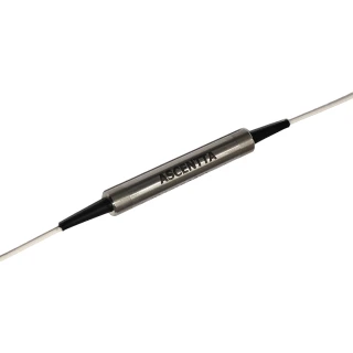
What is a 4-channel TGG-type fiber circulator array and how does it work?
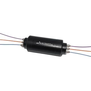
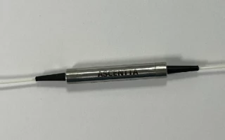
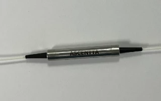
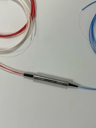
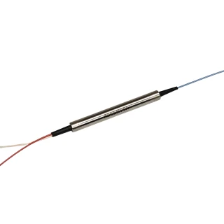
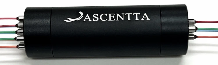
This product is a 4‑channel single‑mode fiber circulator array based on TGG (terbium gallium garnet) Faraday rotators. A fiber circulator is a non‑reciprocal, multi‑port device that routes light sequentially from Port 1→2 and Port 2→3 while strongly suppressing back‑reflections (2→1 or 3→2). In this array, four independent circulators are integrated in one cylindrical package, each designed for a specific wavelength (commonly 532 nm, 650 nm, 780 nm, and 850 nm, or other wavelengths from 532–1100 nm on request). TGG provides strong magneto‑optic rotation, enabling high isolation and low insertion loss across the specified wavelength bands.
What are the typical applications of this 4-channel single-mode circulator array at 532, 650, 780, and 850 nm?
Multi‑wavelength TGG‑type circulator arrays like this are widely used in free‑space and fiber‑based laser systems operating in the visible and NIR. Typical applications include: (1) laser source protection from back‑reflections in diode and solid‑state laser setups at 532, 650, 780, and 850 nm; (2) multi‑channel OCT and biomedical imaging systems; (3) fiber‑optic sensing and interferometry that require directional light routing; (4) research laboratories needing compact multi‑port routing for different visible wavelengths; and (5) integrated subsystems in spectroscopy, metrology, and atomic or quantum optics where isolation and low back‑reflection are critical.
What are the key optical specifications (insertion loss, isolation, return loss, and directivity)?
For this 4‑channel single‑mode TGG circulator array (without connectors) at 23 °C and over all states of polarization (SOP), the key specs are: (1) Insertion loss (1→2 or 2→3): ≤2.5 dB (532 nm), ≤2.3 dB (650 nm), ≤1.8 dB (780 nm and 850 nm); (2) Isolation (2→1 or 3→2): ≥20 dB minimum; (3) Polarization dependent loss (PDL): ≤0.2 dB; (4) Return loss: ≥45 dB; (5) Directivity (1→3 or 3→1): ≥45 dB. These values are comparable to other high‑quality visible‑wavelength circulators on the market and are specified for bare‑fiber units; adding connectors will slightly increase insertion loss and can affect return loss and PDL.
How much optical power can each channel handle at different wavelengths?
The maximum continuous optical power handling depends on the operating wavelength: up to 50 mW at 532 nm, 100 mW at 650 nm, and 150 mW at 780 nm and 850 nm. These limits are typical for precision TGG‑based visible circulators and are chosen to control thermal load and prevent damage to the internal polarizing and Faraday‑rotator elements. For operation near or above these levels, or for pulsed/high‑peak‑power applications, you should consult Ascentta for custom designs or thermal and damage‑threshold guidance.
What environmental and mechanical conditions is this circulator array rated for?
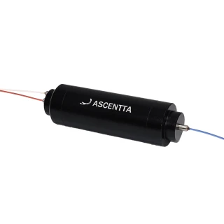
Mechanically, the circulator array comes in a cylindrical package with dimensions of approximately Φ24 mm × 90 mm length, making it suitable for integration into standard optomechanical mounts and system enclosures. The specified operating temperature range is 10 °C to 50 °C, and the storage temperature range is 0 °C to 60 °C. These ranges are consistent with other precision magneto‑optic circulators and help maintain stable isolation, insertion loss, and alignment. For environments outside these ranges, or for vibration/shock‑critical applications, contact Ascentta for ruggedized versions or qualification data.
How do I specify wavelengths, fiber type, cable length, and connectors when ordering?
The standard ordering code format is VCIRA‑XXXX, where you specify: (1) Number of channels: “4” for this 4‑channel array; (2) Channel A/B/C/D wavelength: 532, 650, 780, 850 nm, or “X” for other wavelengths between 532–1100 nm; (3) Cable type: B = 250 µm fiber, L = 900 µm loose tube, H = 3 mm jacket, or X = other types; (4) Fiber length: 10 = 1.0 m, 15 = 1.5 m, 20 = 2.0 m, 30 = 3.0 m, or X = custom length; (5) Connector type: NE = none, FA = FC/APC, FC = FC/PC, SA = SC/APC, SC = SC/PC, ST = ST/PC, LA = LC/APC, LC = LC/PC, or X = other connectors. Because connectors can affect insertion loss, return loss, and PDL, many high‑precision users choose connector‑less pigtails and fusion‑splice in their systems.
Can this circulator array be customized for different wavelengths or system requirements?
Yes. Ascentta explicitly supports custom configurations. In addition to the standard 532, 650, 780, and 850 nm channels, each channel can be customized to any wavelength from 532 nm up to about 1100 nm by using the “X” option in the ordering code. Custom options can include alternative wavelengths (e.g., 637, 730, 905, or 1064 nm), different fiber types (SM fibers for specific bands, polarization‑maintaining options subject to design review), bespoke cable lengths, connector types, and potentially modified power handling or package formats. For applications that differ from these standard specs—such as high‑power lasers, wider temperature ranges, or special mounting needs—you should contact Ascentta directly with your target wavelength, power level, and environmental conditions so they can recommend or design an appropriate configuration.

 Download Data Sheet