


Description
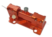
The Motor Driven Polarization Dependent Loss Emulator (PDLE) is a precision-engineered OEM module designed for advanced optical testing and system calibration. This device is ideal for emulating polarization dependent loss (PDL) effects in a wide range of optical components and systems, including attenuators, modulators, array waveguides, fiber Bragg gratings, switches, and fused couplers. By providing a controlled and repeatable PDL environment, the PDLE enables engineers and researchers to accurately quantify and manage PDL budgets within their optical networks.
At the heart of the PDLE is a robust stepper motor and optical block, managed by integrated control firmware. This configuration allows users to set precise PDL values from 0.1 dB up to 20 dB, with fine resolution and rapid response times. The module supports remote operation via multiple computer interfaces, including RS232, I2C, and SPI, ensuring seamless integration into automated test setups and manufacturing lines.
The PDLE is optimized for operation across the C/L Band (1520 nm to 1610 nm), making it suitable for contemporary fiber optic communication systems. It features low insertion loss (<1.0 dB), minimal polarization mode dispersion (<0.5 ps), and high optical return loss (>55 dB), ensuring that it introduces negligible distortion to the optical signal under test. The device is constructed with 9/125 μm single mode fiber and is available with a variety of connector options to suit different deployment needs.
Compact and lightweight, the PDLE module measures just 20.4 mm x 50.6 mm x 72.2 mm and weighs 100 grams, making it easy to integrate into benchtop or rack-mounted systems. Its robust design supports a wide operating temperature range (0°C to 40°C) and can handle input powers up to 500 mW. The PDLE’s rapid response—capable of a full 20 dB change in less than one second—makes it an invaluable tool for real-time PDL compensation, reference source emulation, test equipment calibration, and quality control in optical component manufacturing.
Whether used as a standalone reference or as part of a comprehensive polarization management system, this motor driven PDLE delivers the accuracy, reliability, and flexibility required for demanding optical test and measurement applications.
Motor Driven Polarization Dependent Loss Emulator - OEM
Specifications
| Operating Wavelength Range: | 1520 – 1610 nm |
|---|---|
| Insertion Loss: | 1 dB |
| Polarization Mode Dispersion: | 500 fs |
| Part Number: | PDLE-100-11-1520/1610-9/125-S-3A3A-1-1-MC/RS232 |
| Fiber Type: | 9/125 μm single-mode fiber |
| PDL Dynamic Range: | 0.1-20 dB |
| Optical Return Loss: | > 55 dB |
| Operating Temperature: | 0+40 °C |
| Storage Temperature: | -10 to +60 °C with < 80% non-condensing relative humidity |
| Maximum Input Power: | 500 mW |
| Computer Interface: | RS232, I2C, or SPI |
| Voltage Requirements: | 5 to 12 volts |
| Current Requirements: | 520 mA typical maximum @ 5 V, 182 mA typical maximum @ 12 V |
Got questions about specs? Use the inquiry form to ask.
 Download Data Sheet

Features
- Electrically Controlled Polarization Dependent Loss (PDL) Emulation: Precisely emulate PDL effects in optical systems for accurate testing and calibration.
- Wide Dynamic Range: Adjustable PDL from 0.1 dB to 20 dB with fine resolution, suitable for a variety of testing scenarios.
- Low Insertion Loss: Residual insertion loss of less than 1.00 dB ensures minimal signal attenuation during operation.
- Low Polarization Mode Dispersion (PMD): PMD of less than 0.5 ps for high-fidelity signal transmission and measurement.
- Broad Wavelength Range: Optimized for C/L Band (1520 nm to 1610 nm), compatible with most telecom and photonics applications.
- Fast Response Time: Achieves a 20 dB change in less than 1 second and a 1 dB change in less than 0.1 second for rapid adjustments.
- Multiple Computer Interface Options: Supports RS232, I2C, or SPI for seamless integration into automated test setups and OEM systems.
- Low Optical Return Loss: Greater than 55 dB, reducing back-reflections and improving measurement accuracy.
- Wide Selection of Connectors: Compatible with various connector types to suit different system requirements.
- Compact and Lightweight Design: Small footprint (20.4 mm x 50.6 mm x 72.2 mm) and lightweight (100 g) for easy integration into test benches and OEM modules.
- High Power Handling: Supports maximum input power up to 500 mW for versatile application use.
- Stable Operation: Operates reliably in temperatures from 0°C to 40°C, with storage capability from -10°C to +60°C.
- Low Power Consumption: Operates on 5 to 12 V with low current draw, making it suitable for portable and embedded systems.
- Cost-Effective Solution: Designed for affordability without compromising performance, ideal for both research and production environments.
- Ideal for Multiple Applications: Perfect for PDL compensation, reference PDL source, test equipment calibration, quality control, and measurement in optical networks.
Applications
- PDL Compensation in Optical Networks: Precisely emulate and compensate for polarization dependent loss in fiber optic communication systems, ensuring optimal signal integrity and system performance.
- Reference PDL Source for Calibration: Serve as a stable and repeatable reference PDL source for calibrating polarization dependent loss meters and other test equipment.
- Test Equipment PDL Calibration: Enable accurate calibration of optical test instruments, such as optical spectrum analyzers and polarization analyzers, by providing controlled PDL values.
- Quality Control and Measurement: Support quality assurance processes in the manufacturing of optical components by verifying PDL specifications and tolerances.
- Emulation of PDL Effects in Optical Links: Simulate real-world PDL effects caused by passive and active optical devices (e.g., attenuators, modulators, array waveguides, fiber Bragg gratings, switches, fused couplers) for system margin testing and validation.
- Research and Development: Facilitate R&D activities in photonics and fiber optics by enabling controlled studies of PDL impact on system performance and component behavior.
- Optical System Design and Optimization: Assist engineers in designing robust optical systems by allowing them to test and optimize for PDL tolerance and budget margins.
- Educational and Training Purposes: Provide a hands-on tool for academic and training labs to demonstrate the principles and effects of polarization dependent loss in optical fibers and devices.
- Integration with Automated Test Systems: Seamlessly integrate into automated test setups via RS232, I2C, or SPI interfaces for high-throughput production testing and characterization.
- Component Characterization: Characterize the PDL performance of new or existing optical components under controlled and repeatable conditions.
- Polarization Mode Dispersion (PMD) Studies: Use in conjunction with PMD emulators and analyzers to study the combined effects of PDL and PMD on high-speed optical transmission systems.
- Telecommunications Equipment Manufacturing: Essential for telecom equipment manufacturers to ensure compliance with industry PDL standards and to validate the performance of transmitters, receivers, and amplifiers.
Frequently Asked Questions
What is a Motor Driven Polarization Dependent Loss Emulator (PDLE)?
What are the main applications of the PDLE device?
What is the wavelength range supported by the PDLE?
How does the PDLE achieve high precision in PDL emulation?
What are the key optical performance specifications of the PDLE?
What computer interfaces are available for controlling the PDLE?
What are the power and environmental requirements for the PDLE?
Got more questions? Use the inquiry form to ask the supplier directly.
Similar Products


Your inquiry has been received.
Create an account by adding a password
Why create an account?
- Auto-complete inquiry forms
- View and manage all your past messages
- Save products to your favorites
- Close your account anytime — no hassle