
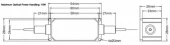
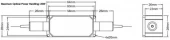
Description
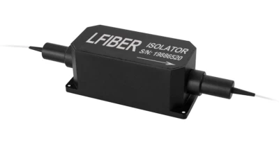
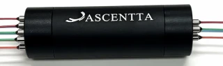
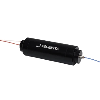
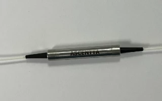
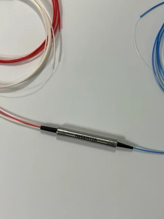
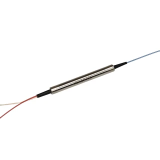
The high power PM fiber optical isolator (1064/1030/980 nm polarization-maintaining optical fiber isolator) is one of the most important passive components. The function of a PM optical isolator is to let a light beam pass through in one direction, that is, the forward direction only, like a one-way traffic. At the same time, the PM optical isolator is able to maintain a well-defined state of polarization (SOP) of the light. The high power PM Isolator (polarization maintaining isolator) is used to prevent reflected light that causes undesirable effects such as frequency instability in laser sources and parasitic oscillation in optical amplifiers.
Notes:
- The high power pm fiber optical isolator is customizable, and the above specifications are subject to change without notice.
- For CW high-power optical interconnection, we recommend fusion splice without connectors.
- For device with connectors, IL is 0.3dB higher, RL is 5.0dB lower, ER is 2.0dB lower.
- Unless otherwise specified, the slow axis of the fiber is aligned with the key of the PM fiber connector.
- Slow axis working and fast axis blocked as standard, while operating on both the slow and fast axis available on request.
- Bare fiber should not support the weight of the connector. So that if any connectors needed, for the pigtail type it’s better to choose the 900μm loose tube jacket instead of the 250μm bare fiber.
- For product customization or special requirements, please contact Lfiber’s sales department for availability.
High Power PM Fiber Optical Isolator
Specifications
| Type Of The Device: | Isolator |
|---|---|
| Operating Wavelength: | 980 nm |
| Max Power: | 10 W |
| Min Isolation: | 25 dB |
| Min. Extinction Ratio At 23℃: | 20 |
| Peak Power: | 10kW, 20kW |
| Fiber Type: | PM1550, PM1310, PM980, Others specified |
| Connector: | None, FC/UPC, FC/APC, SC/UPC, SC/APC, LC/UPC, LC/APC, Others |
| Average Power: | 500mW, 1W, 2W, … 5W, 10W, 20W |
Got questions about specs? Use the inquiry form to ask.
 Download Data Sheet

Features
- High-Power Handling up to 20 W CW
Engineered for demanding industrial and scientific applications, this high power PM isolator supports average optical power up to 20 W and peak power up to 10 kW for nanosecond pulses, minimizing damage risk in high-energy fiber laser systems. - Polarization Maintaining (PM) Design
Utilizes high-quality PM fibers (PM980, PM1310, PM1550, etc.) and precise axis alignment to preserve polarization state, ensuring stable system performance in polarization-sensitive applications such as MOPA fiber lasers and PM fiber amplifiers. - High Isolation for Laser Protection
Delivers typical isolation of 30 dB and minimum 25 dB at 23℃, effectively suppressing back-reflections and feedback. This protects laser sources and upstream components, improving output stability and extending system lifetime. - Low Insertion Loss
Typical insertion loss of only 0.8 dB (max. 1.0 dB at 23℃) allows more of your source power to reach the target. Optimized optical design and coatings help maximize system efficiency in high-power fiber laser chains. - Excellent Polarization Extinction Ratio
Minimum 20 dB extinction ratio at 23℃ ensures efficient rejection of the undesired polarization axis. This is critical for applications requiring stable linear polarization and high contrast, such as interferometry, sensing, and coherent combining. - High Return Loss for Low Back-Reflection
Minimum input/output return loss of 45 dB reduces reflections into the laser cavity, enhancing spectral purity, power stability, and long-term reliability of the optical source. - Optimized for 1064 nm, 1030 nm, and 980 nm
Available at key wavelengths: 1064 nm (Yb fiber lasers), 1030 nm (Yb-based ultrafast/MOPA), and 980 nm (pump diodes and EDFAs). Each version is precisely centered (±5 nm range) for optimal performance at the target wavelength. - Configurable Axis Alignment Modes
Multiple operating configurations are supported:
- Slow axis working and fast axis blocked
- Fast axis working and slow axis blocked
- Both axes working
This flexibility allows precise matching to system polarization requirements. - Robust Mechanical Package
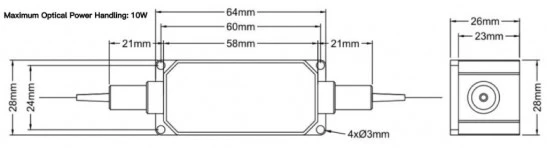
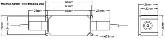
Compact metal housing of 58 × 28 × 26 mm with maximum tensile load of 5 N on fibers. The rugged design is suitable for integration into industrial laser heads, optical benches, and OEM modules. - Stable Performance over Operating Temperature
Operating temperature range of +10℃ to +50℃ and storage from 0℃ to +60℃ ensure stable isolation, insertion loss, and polarization extinction in typical lab and factory environments. - Connector & Pigtail Options
Available with 250 μm bare fiber or 900 μm loose tube pigtails, and a wide selection of connectors, including FC/UPC, FC/APC, SC/UPC, SC/APC, LC/UPC, LC/APC, or customized options. For maximum power and lowest loss, fusion splicing without connectors is recommended. - Designed for CW and Pulsed Fiber Lasers
Suitable for both continuous-wave and nanosecond pulsed operation. High peak power capacity and robust internal optics make it ideal for pulsed MOPA systems, marking, micromachining, and amplifier chains. - High Reliability and Long-Term Stability
Built with high-quality materials, advanced assembly, and strict quality control to maintain isolation, insertion loss, and polarization extinction over time, even under elevated power and environmental stress. - Customizable to Application Needs
Parameters such as center wavelength, power rating, package size, pigtail length, fiber type, connectors, and axis configuration can be customized. This allows optimization for specific OEM systems, research setups, and specialty fiber laser platforms. - Ideal for Advanced Photonics Systems
Well-suited for fiber lasers, MOPA fiber lasers, PM fiber amplifiers, pump laser protection, precision measurement, and test instruments where high power, stable polarization, and strong isolation are critical.
Applications
- High‑Power Fiber Lasers at 1064 nm, 1030 nm, and 980 nm
Ideal as a unidirectional component in industrial, medical, and scientific fiber laser systems operating around 1 µm and 980 nm, preventing destabilizing back‑reflections from downstream optics and workpieces. - MOPA Fiber Laser Systems
Used in Master Oscillator Power Amplifier (MOPA) architectures to protect the seed oscillator and intermediate amplifier stages from back‑propagating ASE and reflections, helping maintain pulse shape, timing, and spectral purity at powers up to 20 W average and kW‑level peak. - Polarization‑Maintaining Fiber Amplifiers
Integrated in PM ytterbium‑doped and other rare‑earth‑doped fiber amplifier chains to enforce forward‑only propagation, protect gain fibers from reflections, and preserve polarization with high extinction ratio. - Ultrafast and Picosecond/Nanosecond Laser Systems
Suitable for pulsed laser systems with ns‑range peak powers up to 10 kW (or specified), ensuring isolation between oscillator, stretcher/compressor, and amplifier stages while maintaining pulse stability. - Seed Laser Protection and Isolation
Installed directly after narrow‑linewidth or single‑frequency PM seed lasers (including 1030/1064 nm CW and pulsed sources) to protect them from back‑reflections coming from isolators, amplifiers, AOMs, EOMs, or free‑space optics. - High‑Power Pump‑Laser Isolation at 980 nm
Deployed with high‑brightness 980 nm pump diodes used for erbium‑doped and ytterbium‑doped amplifiers, preventing back‑reflected light from damaging diodes and stabilizing pump power. - Coherent Beam Combining and Beam Steering Systems
Used in polarization‑sensitive coherent combining setups and active beam steering modules to ensure one‑way light propagation, maintain defined polarization states, and avoid feedback that can disturb phase locking. - Precision Micromachining and Materials Processing
Integrated in high‑power PM laser sources for cutting, drilling, scribing, welding, and surface texturing of metals, ceramics, semiconductors, and polymers, where strong reflections from the workpiece must not couple back into the laser. - Laser Marking, Engraving, and Additive Manufacturing
Applied in 1 µm fiber laser engines for marking and engraving systems (including QR/2D code marking) and metal 3D printing modules to protect the laser from highly reflective metals and dynamically changing load conditions. - Medical and Biomedical Laser Platforms
Used at 1030/1064 nm and 980 nm in therapeutic and surgical systems (e.g., dermatology, photocoagulation, endoscopy, and tissue interaction studies) to isolate the laser source from reflections at fiber couplers, scanners, and tissue interfaces. - Nonlinear Frequency Conversion Stages
Placed before and after nonlinear crystals or waveguides (e.g., for frequency doubling, supercontinuum generation) to protect seed lasers and amplifiers from back‑propagating light and parasitic oscillations while preserving polarization for phase‑matching. - Optical Parametric Amplifier and OPO Pump Isolation
Used in OPA/OPO pump chains at 1030/1064 nm to safeguard pump lasers from reflections originating in nonlinear cavities or tunable output stages, improving long‑term stability and spectral performance. - Fiber‑Based Interferometry and Coherent Detection
Suitable for PM interferometers (Mach‑Zehnder, Michelson) and coherent detection schemes where feedback to the laser must be strictly limited; the PM design ensures stable polarization for high‑visibility interference fringes. - Optical Sensing and LIDAR Systems
Employed in high‑power lidar, range‑finding, and distributed fiber sensing (DTS/DAS) at 1 µm to isolate transmitters from back‑scattered and reflected signal light, increasing system reliability and protecting sensitive sources. - Optical Test and Measurement Instruments
Integrated into high‑power optical test setups and instrumentation—such as power meters, spectrum analyzers, OTDRs, and interferometric measurement benches—to avoid damaging feedback into test lasers and to preserve linear, repeatable measurements. - Quantum Optics and Cold‑Atom Experiments
Used in PM‑fiber‑based quantum optics platforms at 980 nm and 1 µm for trapping, cooling, and manipulation beams, ensuring polarization stability and isolating lasers from reflections off vacuum windows, optics, and atom clouds.
Frequently Asked Questions
What is a high power polarization maintaining (PM) fiber optic isolator and what is it used for?
What are the key specifications and performance parameters of the Lfiber high power PM isolator?
How should I choose the correct wavelength, axis alignment, and fiber type for my application?
What is the difference between bare fiber and 900 µm loose tube pigtails, and when should I use connectors?
How much optical power can the high power PM isolator handle for CW and pulsed operation?
How does axis alignment and polarization work in this PM fiber optic isolator?
What are the recommended installation and handling practices for the Lfiber high power PM isolator?
Got more questions? Use the inquiry form to ask the supplier directly.
Similar Products



Your inquiry has been received.
Create an account by adding a password
Why create an account?
- Auto-complete inquiry forms
- View and manage all your past messages
- Save products to your favorites
- Close your account anytime — no hassle