

Description
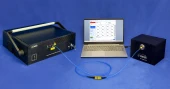
The Automatic Polarization Extinction Ratio (PER) Measurement Test Set is a turnkey semi‑automated solution specifically engineered for high‑density polarization‑maintaining (PM) interconnects such as MPO/MTP® patchcords, V‑groove fiber arrays, and custom multi‑fiber assemblies. Designed to meet the demanding requirements of modern optical communication, coherent transmission, and photonic integration, this system provides fast, accurate, and repeatable characterization of polarization properties across many channels in a single setup. Compared with typical single‑channel PER meters and manual alignment benches used in fiber optic labs and production lines, this integrated platform consolidates the polarization analyzer, motorized alignment stages, and multi‑channel polarized light source into one cohesive test station, dramatically improving throughput and reducing operator‑dependent variability.
At the core of the system is a high‑performance polarization extinction ratio meter featuring a typical wavelength operating range from 1290 nm to 1650 nm, optimized for telecom and datacom windows. It offers an extinction ratio measurement range up to 35 dB with a 40 dB dynamic range, 0.02 dB PER resolution, and ±1 dB accuracy under typical operating conditions. These specifications are well aligned with – and often exceed – many conventional lab‑grade PER meters commonly used for PM patchcord and component testing. The instrument’s angular accuracy of ±0.5 degrees and fine angular resolution support precise characterization of PM fiber alignment in MPO/MTP® connectors and V‑groove arrays, which is critical for ensuring optimal polarization performance in coherent systems and polarization‑sensitive applications.
A distinguishing feature of this test set, compared to standard benchtop PER meters and discrete motorized stages seen across the fiber optics market, is its integrated motorized translation stage system designed specifically for multi‑fiber assemblies. The built‑in stages provide a standard 12 mm travel range with 0.1 μm resolution, enabling automated, repeatable fiber alignment during measurement. Selectable pitch steps such as 125 μm and 250 μm accommodate common fiber spacings found in V‑groove arrays and MPO/MTP® ferrules. This allows users to map channel‑to‑channel performance quickly, without repeatedly repositioning fixtures or re‑terminating test leads. For applications that demand even larger travel or custom spacing, extended travel options can be configured. By combining precision mechanics, polarization analysis, and channel stepping in one instrument, the system reduces setup complexity that typically arises when using separate PER meters, stages, and external controllers.
The multichannel polarized light source is another integral element of this solution. Available with 12, 16, or 24 channels, it supports individual channel control, enabling users to selectively drive and monitor specific fibers within an MPO/MTP® cable or fiber array. In contrast to single‑output polarized lasers or broadband sources that require external splitters and complex routing, this approach offers a clean, direct way to perform multi‑channel PER testing and channel‑by‑channel verification in a production environment. The source is optimized for the same 1290–1650 nm region, ensuring compatibility with standard SM and PM fibers used in telecom, data center, and advanced photonic systems.
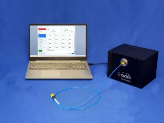
From a usability standpoint, the system is controlled via a Windows‑based software application running on the user’s computer. The intuitive graphical user interface streamlines the workflow of configuring channels, running automated PER scans, and collecting or exporting results. Automated stepping through fibers using predefined pitch settings enables rapid batch testing of multi‑fiber assemblies, while high‑speed relative power updates (up to approximately 650 Hz) and PER update rates around 2.7 Hz provide a responsive measurement experience. Because communication with the hardware is handled via a standard USB interface and does not require specialized drivers or separate motion controllers, integration into existing test benches, manufacturing lines, and R&D labs is straightforward.
The Automatic Polarization Extinction Ratio Measurement Test Set is particularly well suited for environments where both performance and throughput are critical. In fiber optic component manufacturing, it helps qualify MPO/MTP® PM patchcords, V‑groove arrays, and custom fiber assemblies, ensuring that polarization crosstalk and alignment meet tight specifications before shipment. In data centers and high‑speed communication systems, it supports verification and troubleshooting of high‑density PM links used in coherent or polarization‑multiplexed architectures.
OZ Optics Automatic Polarization Extinction Ratio Test Set for MPO MTP
Specifications
| Wavelength Range: | 1290 – 1650 nm |
|---|---|
| Extinction Ratio Range: | 35 – 35 dB |
| Dynamic Range: | 40 dB |
| Extinction Ratio Resolution: | 0.02 dB |
| Part Number: | ER-2000-MC-MPO-1290/1650-1-ER=35 |
| Extinction Ratio Accuracy: | ±1 dB |
| Angular Accuracy: | ±0.5 degrees |
| Angular Resolution: | 0.3 degrees |
| Update Rate (Extinction Ratio): | 2.7 Hz |
| Update Rate (Relative Power): | 650 Hz |
| Standard Travel Range: | 12 mm |
| Travel Resolution: | 0.1 μm |
| Input Optical Power: | 50 µW to 1.0 mW |
| Communication Interface: | USB |
| Input Supply Voltage: | Universal 50/60 Hz 110/220 V AC/DC adapter |
| Dimensions: | 20 x 15.2 x 15.2 cm |
| Weight: | 2.5 kg |
| Operating Temperature: | 10° to 40°C |
| Storage Temperature: | -40° to +80°C |
| Storage Humidity: | <90% RH non condensing |
Got questions about specs? Use the inquiry form to ask.
 Download Data Sheet

Features
- Turnkey Automatic PER Measurement for MPO/MTP® & V-Groove Assemblies
Fully integrated, semi-automated test setup optimized for polarization extinction ratio (PER) testing of MPO/MTP® PM patchcords, V‑groove arrays, and custom fiber arrays – no custom system integration required. - High Extinction Ratio Capability up to 35 dB
Accurately measures polarization extinction ratios up to 35 dB across the 1290–1650 nm range, matching or exceeding typical PER requirements for high‑performance PM fiber components. - Multi-Channel PER Measurement for High-Density Connectors
Designed for multi‑fiber connectors and arrays with configurable 12, 16, or 24 channels, providing simultaneous or sequential PER testing across all channels to significantly reduce test time in production environments. - Built-In Motorized Stages for Automated Fiber Alignment
Integrated, precision motorized translation stages with a standard 12 mm travel range and 0.1 μm resolution automatically align fibers for optimum PER, improving repeatability and minimizing operator dependency. - Selectable Fiber Pitch Steps (125 μm, 250 μm, etc.)
Supports common and custom fiber pitch separations such as 125 μm and 250 μm, enabling compatibility with standard MPO/MTP® ferrules, V‑groove arrays, and custom photonic integrated circuit (PIC) fiber interfaces. - Integrated Multi-Channel Polarized Light Source
Includes a matched multi‑channel polarized source (12, 16, or 24 channels) with individual channel control, ensuring stable, well-defined polarization states for precise PER characterization across all channels. - High Dynamic Range and Fine PER Resolution
Offers a 40 dB dynamic range and a fine 0.02 dB extinction ratio resolution, enabling detection of subtle polarization performance differences critical for advanced coherent and high‑speed communication systems. - Excellent Measurement Accuracy and Angular Control
Delivers ±1 dB PER accuracy, ±0.5° angular accuracy, and 0.3° angular resolution (for MPO/MTP®), ensuring highly repeatable alignment of PM axes and reliable quality control in manufacturing and R&D labs. - Fast Measurement Update Rates for Production Throughput
Provides an extinction ratio update rate of 2.7 Hz and a relative power update rate of 650 Hz, allowing rapid optimization and pass/fail evaluation for high‑volume testing of multi‑fiber assemblies. - Wide Operating Wavelength Range: 1290–1650 nm
Supports key telecom and datacom bands from 1290 nm to 1650 nm, making it suitable for testing components used in CWDM, DWDM, O-band, C-band, and L‑band coherent systems, as well as fiber sensing applications. - Intuitive Windows-Based Graphical User Interface
User‑friendly Windows application provides real‑time PER visualization, data logging, channel management, and automated test sequences, simplifying operation for both production technicians and R&D engineers. - USB Connectivity – No Extra Drivers or Controllers
Simple USB interface to a standard PC, with no proprietary controller hardware or special driver installation required, streamlining setup and integration into existing test benches and manufacturing lines. - Configurable Fiber Port Adaptors
Both the PER meter and the polarized source can be equipped with customer‑specified fiber port adaptors, supporting MPO/MTP®, V‑groove, and customized connector formats commonly used in PIC coupling and fiber arrays. - Optimized for PM Fiber & Coherent Communication Systems
Specifically designed for PM fiber patchcords and arrays used in coherent transmission, high‑speed data centers, and advanced optical communication links where accurate polarization control and low crosstalk are critical. - Ideal for Manufacturing, R&D, and Troubleshooting
Suited for fiber optic component manufacturing, data center interconnects, PIC packaging, fiber sensing systems, and system troubleshooting, replacing slower manual PER test methods with a more consistent automated solution.
Applications
- High-Volume Fiber Optic Component Manufacturing – Ideal for production lines manufacturing MPO/MTP® PM patchcords, V‑groove arrays, and custom fiber arrays where fast, repeatable polarization extinction ratio (PER) testing is required to meet tight quality control and yield targets.
- Assembly and Certification of MPO/MTP® Trunk Cables – Enables automatic PER characterization of multi‑fiber MPO/MTP® backbone cables used in data centers and enterprise networks, ensuring proper polarization alignment for high‑speed links before deployment.
- Testing of V‑Groove Fiber Arrays – Designed for precise PER measurements on multi‑channel PM fiber arrays in v‑groove blocks, supporting manufacturers of array-based components for photonic integrated circuits and silicon photonics packaging.
- Polarization Qualification of PM Patchcords and Pigtails – Provides rapid verification of extinction ratio, angular alignment, and stability of individual and multi‑channel polarization‑maintaining patchcords and pigtails over the 1290–1650 nm telecom band.
- Silicon Photonics and Photonic Integrated Circuit (PIC) Testing – Supports alignment and PER characterization of fiber‑to‑chip interfaces, array couplers, grating couplers, and PIC I/O blocks where accurate input/output polarization states are critical.
- Coherent Optical Communications Development – Used to qualify PM fibers and assemblies feeding coherent transceivers, I/Q modulators, local oscillators, and coherent receivers, minimizing polarization‑related penalties in advanced modulation formats (QPSK, QAM, etc.).
- High-Speed Data Center Interconnects – Ensures polarization‑related performance of multi‑fiber links in 40G/100G/400G+ parallel optics and coherent pluggables, improving link stability and reducing bit‑error rates in hyperscale and cloud data centers.
- DWDM and Advanced Modulation Test Labs – Provides reliable PER measurements for PM components integrated into DWDM systems, wavelength‑selective switches, and testbeds evaluating polarization‑dependent effects under complex modulation schemes.
- Fiber Laser and Amplifier Systems Using PM Fiber – Verifies extinction ratio of PM delivery fibers, combiners, and couplers used in fiber lasers, EDFAs, and Raman amplifiers, ensuring stable polarization for power scaling and noise reduction.
- Polarization-Sensitive Sensor Systems – Suitable for manufacturers and integrators of fiber‑optic gyroscopes, interferometric sensors, and polarization‑based sensing systems requiring accurate control of PM fiber orientation and PER.
- Quantum Communications and Quantum Photonics – Supports alignment and qualification of PM fiber arrays and patchcords used in polarization‑encoded quantum key distribution (QKD), entangled photon distribution, and quantum networking experiments.
- Integrated Optics and Planar Lightwave Circuit (PLC) Packaging – Assists in aligning multi‑fiber PM arrays to PLC chips, waveguide arrays, and polarization‑sensitive splitters/couplers, allowing precise PER characterization during packaging and final test.
- OEM Module and Transceiver Manufacturing – Provides automated PER test capability for multi‑channel PM subassemblies in pluggable transceivers, coherent CFP/QSFP modules, and line cards, supporting both R&D and volume manufacturing environments.
- Polarization Alignment in Test & Measurement Racks – Used as a turnkey polarization verification stage in automated test equipment (ATE) racks for telecom and datacom device characterization, simplifying integration via USB control.
- Component or System Troubleshooting – Enables quick identification of polarization‑related issues such as poor PM fiber alignment, connector damage, or stress‑induced axis rotation in complex fiber assemblies or deployed systems.
- Incoming Inspection and Vendor Qualification – Ideal for verifying the PER performance of incoming PM fiber cables, v‑groove arrays, and custom assemblies from different suppliers against internal specifications and SLAs.
- Research and Development in Polarization Optics – Serves as a flexible platform in R&D labs studying polarization effects, polarization‑dependent loss, and crosstalk in new PM fibers, connectors, and photonic devices.
- Educational and Training Laboratories – Useful for universities and training centers teaching polarization optics, coherent communications, and silicon photonics, giving students hands‑on experience with automated PER measurements.
Frequently Asked Questions
What is the Automatic Polarization Extinction Ratio Measurement Test Set for MPO/MTP PM fiber patchcords and V‑groove assemblies used for?
What polarization extinction ratio performance and measurement accuracy does this system provide?
How does the automatic PER measurement work for MPO/MTP and V‑groove fiber arrays?
What fiber types, channel counts, and pitches can this PER test set support?
What are the key hardware specifications, including travel range, resolution, and input power levels?
What software and connectivity options are available for automation and data logging?
How does this automatic PER test set compare to manual polarization extinction ratio measurement solutions?
Got more questions? Use the inquiry form to ask the supplier directly.
Similar Products


Your inquiry has been received.
Create an account by adding a password
Why create an account?
- Auto-complete inquiry forms
- View and manage all your past messages
- Save products to your favorites
- Close your account anytime — no hassle