
Description
These fiber optic polarizers are precision-engineered components designed to convert light from a source or fiber into a well-defined linear polarization state and efficiently launch it into an output fiber. By combining high-quality input and output fiber collimators with a carefully selected plate polarizer, they deliver excellent polarization control over a wide spectral range from 400 nm to 2050 nm. This makes them suitable for both visible and infrared applications, covering common telecom windows at 1310 nm and 1550 nm as well as specialty wavelengths used in sensing, imaging, and laser systems.
A key performance metric for these devices is their high power extinction ratio, with values up to 30 dB. The power extinction ratio describes the ratio between the maximum and minimum transmitted power as the input polarization state is rotated. In practice, this indicates how effectively the polarizer rejects the unwanted polarization component. When polarization-maintaining (PM) fiber is used at the output, the resulting output polarization extinction ratio depends not only on the intrinsic polarizer quality but also on the alignment of the PM fiber axes and the extinction ratio of the PM fiber itself. In all cases, the power extinction ratio equals or exceeds the polarization extinction ratio, providing a robust foundation for demanding polarization-sensitive systems.
Compared with typical in-fiber or planar polarizers found across the photonics market, these units are distinguished by their combination of low insertion loss, low back reflection, and broadband operation. Broadband plate polarizers are employed so that the performance remains stable over bandwidths spanning several hundred nanometers, enabling a single component to cover multiple operating bands. For instance, the same device can be specified to operate from 1300 nm through 1600 nm without sacrificing extinction performance, a capability that is particularly attractive for swept-source systems, tunable lasers, and multi-wavelength measurement platforms.
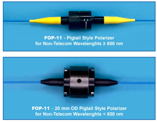
The product line covers six mechanical formats, giving designers considerable flexibility when integrating into existing fiber assemblies or compact instruments. The original 12.5 mm and 20 mm diameter pigtail-style housings are especially well suited for non-telecom wavelengths and for custom configurations, including high-power setups where larger optical apertures and improved thermal management are advantageous. Using these larger formats, polarizers capable of handling several watts of optical power have been realized, aligning them with the requirements of high-power fiber lasers, optical amplifiers, and nonlinear optics experiments.
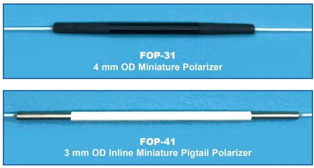
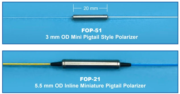
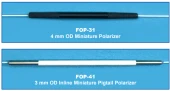
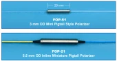
For applications in telecommunications, integrated optics, and other space-constrained environments, smaller diameters are available, including 5.5 mm, 4 mm, and ultra-compact 3 mm outer diameter versions. These miniature pigtail and inline styles are optimized for standard telecom wavelengths and are ideal where board-level or module-level integration is needed, such as in fiber optic gyroscopes, coherent receivers, and compact interferometers. The 3 mm form factor, in particular, is designed for scenarios where every millimeter of space matters, allowing advanced polarization control to be added to densely packed optical subsystems without compromising performance.
By supporting single-mode, multimode, polarization-maintaining, and hybrid fiber configurations, the polarizers address a broad spectrum of system architectures. In fiber amplifiers and laser cavities, they enable stable polarization selection, reducing noise and improving beam quality. In interferometric sensors, fiber gyroscopes, and OCT systems, they ensure well-defined polarization states that translate into improved signal contrast and measurement repeatability. For metrology and R&D labs, they serve as reliable building blocks for measuring polarization extinction ratio, characterizing components, and conditioning polarization states in complex experimental setups.
Overall, these fiber optic polarizers combine rugged, compact housings with high extinction ratios, low loss, low back reflection, and wide wavelength coverage. Their range of sizes and fiber options allows seamless integration into both prototype and production systems, from precision laboratory instruments to field-deployed sensors and telecom infrastructures, wherever accurate and stable polarization control is a critical design requirement.
Polarizers - Fiber Optic
Specifications
| Center Wavelength: | 1550 nm |
|---|---|
| Operating Wavelength Range: | 400 – 2050 nm |
| Typical Insertion Loss: | 0.5 dB |
| Min Return Loss: | 40 dB |
| Typical Extinction Ratio: | 30 dB |
| Housing Diameter (mini Pigtail Polarizer): | 3 mm OD |
| Housing Diameter (inline Miniature Pigtail Polarizer): | 3 mm OD |
| Housing Diameter (inline Mini Pigtail Polarizer): | 5.5 mm OD |
| Housing Diameter (miniature Polarizer): | 4 mm OD |
| Housing Diameter (pigtail Style Polarizer): | 12.5 mm OD |
| Housing Diameter (pigtail Style Polarizer): | 20 mm OD |
| Supported Wavelengths (non-telecom, Version 1): | ≥ 650 nm |
| Supported Wavelengths (non-telecom, Version 2): | < 650 nm |
| Supported Telecom Wavelengths: | 1310 nm and/or 1550 nm |
| Maximum Transmitted Power (typical Capability): | several Watts |
Got questions about specs? Use the inquiry form to ask.
 Download Data Sheet

Features
- High-Performance Fiber Optic Polarization – Precisely polarizes light from a source or fiber and launches it into an output fiber, enabling accurate control of polarization state for advanced photonic systems.
- Wide Wavelength Coverage (400–2050 nm) – Supports a broad spectral range from visible to near‑infrared, ideal for applications spanning sensing, test and measurement, telecom, and industrial photonics.
- High Extinction Ratio up to 30 dB – Delivers strong polarization discrimination for stable and clean polarized outputs, improving signal quality and system performance in interferometric and sensing setups.
- Low Insertion Loss – Engineered for minimal optical loss through the device, preserving source power and maximizing system efficiency, especially important in low‑signal or long‑haul configurations.
- Low Back Reflection – Designed to minimize return loss and back reflections, protecting sensitive laser sources and enhancing stability in high‑precision optical networks and measurement systems.
- Supports SM, MM, and PM Fibers – Available with single‑mode, multimode, polarization‑maintaining, and various fiber combinations to match a wide range of architectures including fiber amplifiers, gyroscopes, and OCT systems.
- Broadband Polarizer Design – Utilizes plate polarizers optimized for broadband operation so that power extinction ratio is maintained over several hundred nanometers (e.g., a single device can cover 1300–1600 nm), reducing the need for multiple narrowband components.
- Rugged and Compact Housing – Robust mechanical design withstands demanding lab, industrial, and field environments while maintaining precise optical alignment and long‑term stability.
- Miniature and Space-Saving Options – Offered in very small footprints, including 3 mm OD and other miniature housings, ideal for compact instruments, high‑density optical benches, and embedded OEM modules.
- Multiple Package Styles – Available in inline and pigtail configurations (e.g., FOP‑51, FOP‑21, FOP‑31, FOP‑41, FOP‑11 families) to integrate seamlessly into both fiber‑based and free‑space coupled systems.
- High-Power Handling Capability – Larger form factors (such as 20 mm OD versions) are well suited for high‑power applications; designs have been demonstrated to transmit several watts of optical power with reliable performance.
- Optimized for Non‑Telecom and Telecom Bands – Specialized variants for non‑telecom wavelengths ≥ 650 nm and < 650 nm, as well as models optimized for 1310 nm and 1550 nm, enable precise polarization control across key laser and telecom lines.
- Excellent Polarization Extinction Performance – When used with polarization‑maintaining output fiber, delivers a high polarization extinction ratio, dependent on polarizer quality, fiber alignment, and PM fiber extinction ratio, ensuring well‑defined polarization states.
- Flexible Configuration for System Design – Six standard size options and custom configurations available to match different optical layouts, beam diameters, and mounting requirements.
- Low Cost, High Value – Combines strong polarization performance, broad wavelength coverage, and robust packaging in a cost‑effective solution suitable for OEM integration and volume deployment.
- Ideal for Precision Photonics Applications – Well suited for fiber optic gyroscopes, fiber amplifiers, polarization conditioning stages, interferometric sensors, OCT systems, integrated optics experiments, and polarization‑sensitive measurement setups.
Applications
- Fiber Optic Gyroscopes (FOGs)
Used to generate and maintain a single, well‑defined polarization state in interferometric fiber gyroscopes, improving bias stability, sensitivity, and long‑term drift performance in navigation systems for aerospace, marine, and autonomous platforms. - Erbium‑Doped Fiber Amplifiers (EDFAs) and Other Fiber Amplifiers
Employed before, within, and after amplifier stages to control polarization‑dependent gain, reduce polarization mode dispersion, and stabilize output power in telecom and CATV links, high‑power fiber laser pump paths, and pre‑amplifier chains. - Polarization Extinction Ratio (PER) Conditioning in Optical Systems
Integrated into optical setups to enhance and stabilize the polarization extinction ratio of signals, improving signal‑to‑noise ratio and minimizing polarization‑induced fading in coherent communication systems and long‑haul fiber links. - Measurement of Polarization Extinction Ratio
Used as a reference polarizing element in test benches and metrology setups to characterize PER of polarization‑maintaining (PM) fibers, components, and integrated photonic devices across broad wavelength ranges. - Optical Fiber Sensors
Implemented in intensity, phase, and wavelength‑encoded fiber sensors to define the input polarization state and to maximize sensitivity in systems such as fiber Bragg grating (FBG) sensors, temperature and pressure probes, and chemical or biochemical sensors. - Interferometric Fiber‑Optic Sensors
Critical in Mach‑Zehnder, Michelson, and Sagnac interferometers where stable polarization is needed to maintain fringe visibility, enabling precise measurements of strain, acoustic waves, seismic activity, rotation, and other environmental perturbations. - Optical Coherence Tomography (OCT) Systems
Used to set and maintain a defined polarization state in OCT sample and reference arms, improving image contrast, axial resolution, and enabling polarization‑sensitive OCT (PS‑OCT) for tissue birefringence mapping in medical and industrial imaging. - Integrated Optics and Photonic Integrated Circuits (PICs)
Provide controlled polarization inputs to waveguides, modulators, splitters, and other on‑chip photonic elements, allowing accurate characterization of TE/TM modes and optimizing coupling efficiency between fiber and planar lightwave circuits. - Coherent Communication and Modulation Formats
Applied in coherent receivers and transmitters to manage polarization for advanced modulation schemes (QPSK, QAM, DP‑QPSK), reducing polarization‑related penalties and enhancing performance in high‑capacity DWDM networks. - Quantum Optics and Quantum Communication
Used to prepare and filter well‑defined polarization states for single‑photon and entangled‑photon experiments, quantum key distribution (QKD) links, and quantum sensing setups relying on polarization‑encoded qubits. - Laser Polarization Control and Stabilization
Deployed at the output of diode lasers and fiber lasers to achieve a fixed linear polarization, reduce polarization noise, and improve downstream performance in nonlinear frequency conversion, spectroscopy, and material processing. - Nonlinear Optics and Frequency Conversion
Ensure proper polarization orientation for efficient second‑harmonic generation, sum‑ and difference‑frequency generation, four‑wave mixing, and supercontinuum generation in nonlinear fibers and crystals that exhibit strong polarization dependence. - Polarization‑Sensitive Imaging and Microscopy
Provide highly polarized illumination for polarization‑dependent contrast techniques such as polarization microscopy, birefringence imaging, and stress analysis in biological samples, crystals, polymers, and micro‑structured materials. - Optical Sensor Interrogation Units
Incorporated in interrogators for FBG arrays and interferometric sensor networks to standardize input polarization, ensuring repeatable wavelength and phase measurements in structural health monitoring and oil & gas sensing. - Test & Measurement Instrumentation
Integrated into benches and commercial test systems (OTDR setups, spectrum analyzers, network analyzers) for component characterization where a stable and known polarization state is required for accurate PDL, PMD, and insertion loss measurements. - Telecommunications and Data Center Links
Used in specialty links and experimental systems to reduce polarization‑related impairments, especially where PM fibers, coherent detection, or advanced MIMO polarization processing are being evaluated or deployed.
Frequently Asked Questions
What is an OZ Optics fiber optic polarizer and how does it work?
What is the difference between power extinction ratio and polarization extinction ratio in these fiber optic polarizers?
Which wavelengths and fiber types are supported by OZ Optics FOP‑series fiber optic polarizers?
How do I select the right FOP model (FOP‑11, FOP‑21, FOP‑31, FOP‑41, or FOP‑51) for my application?
What extinction ratio and insertion loss can I expect from OZ Optics fiber optic polarizers?
Can these fiber optic polarizers handle high optical power, and what mechanical sizes are available?
What are typical applications of OZ Optics fiber optic polarizers and how do they improve system performance?
Got more questions? Use the inquiry form to ask the supplier directly.
Similar Products


Your inquiry has been received.
Create an account by adding a password
Why create an account?
- Auto-complete inquiry forms
- View and manage all your past messages
- Save products to your favorites
- Close your account anytime — no hassle