
Description
These optical delay lines are high‑performance fiber‑based devices designed to provide precisely controlled time delays for light signals over a wide wavelength range of 400–2000 nm. By combining high quality input and output fiber collimators with a carefully engineered free‑space propagation region, the delay lines enable exceptionally fine control of optical path length and therefore signal timing. The result is low insertion loss and sub‑picosecond resolution, making them ideal for modern high‑speed photonics, test and measurement, and coherent communication systems.
At the core of each delay line is an optical architecture that projects light from an input fiber into free space, controls the distance traveled in air, and efficiently couples the light back into an output fiber. The optical path length is varied either by changing the physical separation between the collimators or by reflecting the beam from a precisely positioned movable reflector. Because the speed of light in free space is well known and the mechanical motion is accurately controlled, the devices provide a direct and repeatable relationship between mechanical displacement and temporal delay, which can be calibrated in picoseconds for straightforward use in timing‑critical experiments and systems.
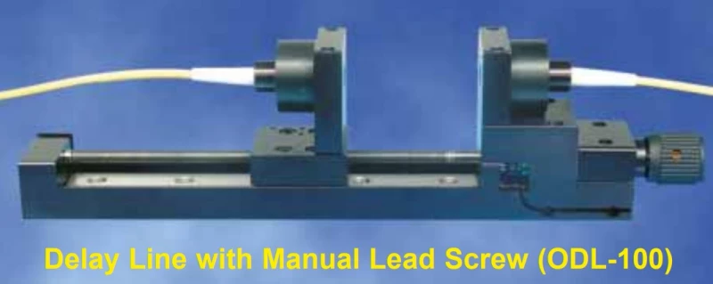
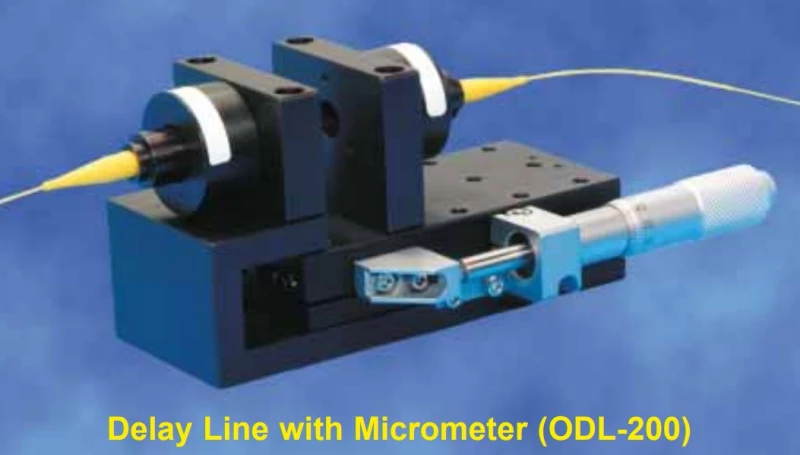
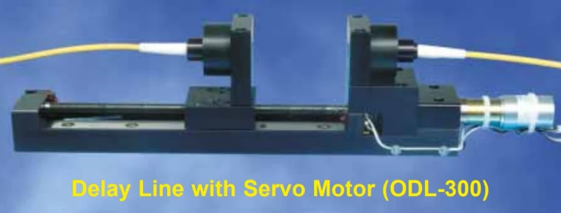
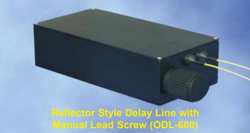
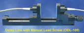
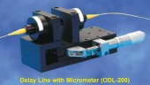
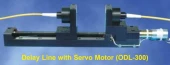
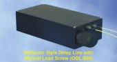
Broad Product Range Covering Manual, Motorized, and Miniature DesignsThe delay line family includes several mechanical formats tailored to different integration needs and performance requirements. Lead screw‑based models, such as the ODL‑100 and ODL‑300, deliver stable, linear motion with excellent repeatability, and are available in manual or motorized configurations. For users who prefer direct micrometer adjustment, the ODL‑200 offers intuitive, fine‑resolution control suitable for benchtop experiments and quick optical path optimization. Reflector‑style designs, including manual and servo‑driven versions of the ODL‑600 and ODL‑650, extend the delay range while preserving low loss and robust alignment, supporting ranges from tens of picoseconds up to over 1200 picoseconds.
For applications where space is at a premium, the ODL‑700 miniature delay line provides up to approximately 13 picoseconds of delay in a footprint not much larger than a standard fiber patch connection. This compact design is particularly attractive for OEM integration in instruments such as portable interferometers, compact optical coherence tomography systems, and embedded fiber sensors, where mechanical stability, ease of mounting, and minimal added insertion loss are essential.
Fiber Options for Singlemode, Multimode, and Polarization Maintaining OperationThese optical delay lines are available with singlemode, multimode, or polarization maintaining (PM) fibers to match a broad variety of system architectures. For polarization‑sensitive applications, PM implementations typically use PANDA‑style fibers, offering excellent polarization extinction and stability. This is especially important for coherent detection, interferometric metrology, and polarization‑encoded communication schemes where any unwanted polarization rotation or fluctuation directly degrades signal quality and measurement accuracy.
The ability to build delay lines from alternative PM fiber structures or customer‑supplied fibers increases flexibility for specialized use cases, such as non‑standard operating wavelengths, custom numerical apertures, or fibers optimized for specific dispersion characteristics. This customizable fiber approach aligns the delay line’s behavior with the rest of the optical system, improving coupling efficiency, polarization alignment, and long‑term reliability in both laboratory and industrial environments.
Manual and Electrically Controlled Options with Sub‑Picosecond ResolutionUsers can select between purely manual adjustment and advanced electrically controlled versions depending on their workflow and automation needs. Manual devices rely on precision lead screws or micrometers, delivering smooth mechanical motion and stable delay settings suitable for alignment tasks, static operating points, or occasional reconfiguration. The mechanical assemblies are engineered for low backlash and good thermal stability, ensuring that the set delay remains consistent over time and under typical laboratory conditions.
Electrically controlled delay lines incorporate servo motors with position encoders, enabling closed‑loop motion control with sub‑micron positioning accuracy. This translates into temporal resolution better than 0.003 picoseconds, more than sufficient for characterizing ultrafast pulses, compensating path length fluctuations, or conducting automated scan routines.
Optical Delay Lines with Sub-Picosecond Resolution
Specifications
| Travel Range: | 50 mm |
|---|---|
| Resolution: | 635 um |
| Delay Range: | 167 psec |
| Delay Resolution: | 2 psec |
| Delay Range (standard): | 167 ps |
| Delay Range (extended Manual Reflector Style): | 330 ps or 600 ps |
| Delay Range (extended Reflector Style With Servo Motor): | 330 ps, 600 ps or 1200 ps |
| Delay Range (miniature Style): | up to 13 ps |
| Resolution (electrically Controlled Versions): | submicron (<0.003 ps) |
| Wavelength Range: | 400–2000 nm |
| Control Interface (electrically Controlled): | RS-232 and TTL inputs |
| Fiber Types: | singlemode, multimode, polarization maintaining (PANDA and others) |
Got questions about specs? Use the inquiry form to ask.
 Download Data Sheet

Features
- Ultra-Precise Optical Delay Control – Sub-picosecond temporal resolution (better than 0.003 ps with motorized versions) enables fine adjustment of optical path length for demanding timing‑critical experiments and systems.
- Wide & Flat Spectral Operating Range (400–2000 nm) – Supports a broad wavelength span from visible to near‑IR, making the delay lines suitable for telecom bands (O, C, L), ultrafast lasers, broadband sources, and OCT systems without frequent re‑optimization.
- Low Insertion Loss, High Signal Integrity – Precisely engineered fiber collimators and free‑space optics deliver low insertion loss and minimal back reflections for improved system dynamic range and stable measurements.
- Expanded Delay Range up to >1200 ps – New extended‑range models provide optical delays from a few picoseconds up to over 1200 ps (e.g., 167 ps, 330 ps, 600 ps, 1200 ps options), covering short‑ and long‑range delay requirements in one product family.
- Polarization Insensitive and PM Options – Available in standard singlemode, multimode, and polarization maintaining (PM) fibers (PANDA‑style and other structures on request), enabling use in polarization‑sensitive and polarization‑diverse systems.
- Electrically Controlled & Manual Versions – Choose between fully motorized delay lines with servo motor, encoders, RS‑232/TTL control, or manual micrometer and lead‑screw models for simple, robust bench‑top operation.
- High‑Resolution Motorized Servo Stages – Motorized ODL units (e.g., ODL‑300, ODL‑650) use precision servo motors with integrated encoders, providing repeatable, backlash‑compensated positioning and software‑addressable time delay in calibrated picosecond units.
- Compact Miniature Delay Line Option – Miniature models (e.g., ODL‑700) offer up to ~13 ps delay in an extremely compact package, occupying only slightly more space than a standard fiber connector for easy integration into dense optical setups.
- Robust Mechanical Design with Integrated Safety Stops – Home and end‑of‑travel sensors prevent over‑travel and mechanical damage, while precision rails and bearings ensure stable, low‑drift operation over time.
- Flexible Fiber Interfaces & Connectivity – Supports common connector types and customer‑specified fibers; OZ Optics can build with user‑supplied fiber or alternative PM structures to match existing networks and experimental platforms.
- Free‑Space Delay Architecture – Input/output fiber collimators project light into free space and recouple it back into fiber, enabling highly linear, repeatable delay control based on physical path length and compatible with a wide range of wavelengths and beam qualities.
- Multiple Mechanical Styles for Different Use Cases – Available as reflector‑style delay lines, micrometer‑based stages, manual or motorized lead‑screw assemblies, and extended‑range configurations, so users can optimize for range, footprint, and adjustment method.
- Ideal for High‑Speed Communications & PMD Compensation – Designed for use in coherent telecom systems and high‑bit‑rate test beds, offering precise delay and polarization management for PMD/dispersion emulation and compensation.
- Optimized for Interferometry & Coherence Control – High stability and sub‑ps resolution make these ODLs well suited for interferometric sensors, optical coherence tomography (OCT), optical spectrum analyzers, and general coherence‑length tuning.
- Computer & Lab‑Friendly Integration – RS‑232 control and simple TTL input signals allow straightforward integration into automated test systems, data acquisition setups, and research labs requiring programmable optical delay lines.
- Application‑Proven in Research and Industry – Used worldwide in ultrafast optics labs, fiber‑optic sensing, coherent detection, and telecom development, providing a mature and reliable solution for precise optical delay management.
Applications
- Polarization Mode Dispersion (PMD) Compensation in High-Speed Optical Networks
Used to finely adjust relative delays between polarization components in long-haul and metro DWDM systems, 40G/100G/400G coherent links, and ultra‑high bit‑rate testbeds, improving eye diagrams, Q‑factor, and BER performance. - Optical Coherence Tomography (OCT) and Time‑Domain Imaging Systems
Provides precise reference‑arm path length control in time‑domain and swept‑source OCT, enabling depth scanning, coherence gating, axial resolution tuning, and calibration of medical and industrial OCT scanners. - Interferometric Sensors and Fiber-Optic Sensing
Enables phase and path‑length matching in interferometric configurations such as Mach‑Zehnder, Michelson, Fabry–Pérot, Sagnac, and common‑path sensors used for strain, temperature, vibration, and acoustic sensing. - Coherent Optical Telecommunications and Coherent Detection Systems
Aligns optical path lengths between signal and local oscillator in coherent receivers, supports polarization‑multiplexed QPSK/QAM formats, and optimizes DSP performance in advanced coherent transceivers and test setups. - Optical Spectrum Analyzers and Coherent Optical Spectrum Measurements
Incorporated into scanning interferometer‑based spectrum analyzers and Fourier transform optical spectrum analyzers (FT‑OSA) to set the interferometer delay, spectral resolution, and free spectral range. - Optical Time‑Domain Reflectometry (OTDR) and Time‑Resolved Measurements
Used to calibrate and offset reference paths in OTDR and time‑correlated single‑photon counting (TCSPC) systems, improving timing alignment and temporal resolution in backscatter and fluorescence measurements. - Pump–Probe, Ultrafast, and Femtosecond Laser Experiments
Provides sub‑picosecond delay adjustment between pump and probe pulses in ultrafast spectroscopy, nonlinear optics, transient absorption, and carrier dynamics studies, enabling precise control of temporal overlap. - Optical Signal Processing and All‑Optical Logic
Implements controlled path‑length differences for optical buffers, logic gates, clock recovery, temporal multiplexing/demultiplexing, and waveform shaping in research and prototype optical processing circuits. - Optical Coherence and Interferometer Alignment
Used to match optical path lengths in white‑light and laser interferometers, enabling fringe contrast optimization, coherence length characterization, and calibration of metrology interferometers. - Time‑Division Multiplexing (TDM) and OTDM System Development
Adds controlled delays between channels in high‑speed TDM/OTDM systems to manage channel spacing, skew compensation, bit‑walk‑off, and timing synchronization in optical bit‑interleaving experiments. - Calibration of Photonic Components and Test & Measurement Systems
Serves as a tunable reference delay in characterization of modulators, detectors, switches, and integrated photonic circuits, enabling group delay, jitter, and timing skew measurements in lab and production testing. - Quantum Optics and Quantum Communication Experiments
Aligns arrival times of single photons or entangled photon pairs at beam splitters in Hong‑Ou‑Mandel interference, time‑bin entanglement, and quantum key distribution (QKD) setups, optimizing visibility and coincidence rates. - Fiber Laser and Mode‑Locked Laser Optimization
Used to adjust cavity length, synchronization between multiple cavities, and timing of reference pulses in mode‑locked fiber lasers, regenerative amplifiers, and frequency comb systems. - Coherent LIDAR, FMCW LIDAR, and Ranging Systems
Balances or offsets optical paths in coherent and FMCW LIDAR, enabling calibration of range resolution, phase matching, and heterodyne detection performance. - Multipath Emulation and Channel Simulation
Emulates controlled path delays in fiber‑based RF‑over‑fiber and microwave photonics testbeds to model multipath channels, delay spreads, and environmental variations. - Optical Synchronization of Distributed Systems
Provides fine timing alignment between remote optical clocks, triggers, and reference signals in large‑scale experiments such as accelerators, telescopes, and synchronized laser facilities. - Polarization‑Maintaining (PM) System Alignment
In PM configurations, used in conjunction with PM couplers, splitters, and interferometers to maintain and finely tune path length and state of polarization in coherent PM systems from 400–2000 nm.
Frequently Asked Questions
What is an OZ Optics fiber optic delay line and how does it work?
What delay range and resolution do OZ Optics optical delay lines provide?
Which fiber types and wavelength ranges are supported by these optical delay lines?
What is the difference between manual and electrically controlled (motorized) OZ Optics delay lines?
Are OZ Optics delay lines polarization sensitive or suitable for polarization maintaining applications?
What are typical applications for OZ Optics fiber optic delay lines?
How do I control and integrate an OZ Optics motorized optical delay line into my setup?
Got more questions? Use the inquiry form to ask the supplier directly.
Your inquiry has been received.
Create an account by adding a password
Why create an account?
- Auto-complete inquiry forms
- View and manage all your past messages
- Save products to your favorites
- Close your account anytime — no hassle