Ring laser gyroscopes have come a long way since the first prototypes. The first gyrocompass was co-invented in 1908 by Elmer Sperry, a.k.a “the father of modern navigation technology,” and Herman Anschütz-Kaempfe. Since then, gyroscopes have been constantly improved through R&D due to their usefulness in navigation and transportation applications. Specifically, these gyros can provide guidance to stabilize aircraft flights or even autopilot operations. For instance, in June 1914 Lawrence Sperry (Elmer Sperry’s son) ran a demonstration flight where he stood up in the cockpit, allowing a gyroscopic autopilot to stabilize the plane for a moment.
Immediately, much interest was gained in the potential for gyroscopes and autopilot technologies. With autopilot, pilots can relieve fatigue and strain on long flights. Thus, it is ideal for commercial applications, can reduce human error, and improve safety on board. Following mechanical gyroscopes, the first ring laser gyroscope was invented in 1963 by Mecek and Davis. Today, laser gyros have replaced their mechanical gyroscope predecessors due to their higher level of accuracy, maintenance, and cheap cost. In fact, about half of the ring laser gyro market today is the military for aeronautic devices.
Equally important, ring laser gyros are good for applications where GPS may not reach. Gyroscope technology does not rely on satellite signals or other frequencies. Namely, enemy electronic warfare is increasingly becoming more advanced and utilized more often. However, self-contained gyroscopes can protect these missions from any unwanted electronic interference. Since commercialization of laser gyros began in the 1980s, they have become the most popular laser device in the aerospace industry. In this article we will explore the operating principle of ring laser gyroscopes and two different navigation and munition transportation applications.
Principle of Ring Laser Gyroscopes (RLG)
The ring laser gyroscope’s function is to find the orientation of an object in inertial space at any time. Regular gyroscopes do this by a method similar to the way the human ear detects motion. Sensors detect motion through referencing disturbances to another body in an inertial frame. To illustrate, the fluids in the human ear act as the inertial body and hairs in the ear act as the sensors. In particular, the inertial body for ring laser gyroscopes are actually completely immobile. Now we will discuss what this immobile body is in RLGs and how they process orientations through the Sagnac effect.
Sagnac Effect
First, a ring laser gyroscope is set up as a ring interferometer. This interferometer has narrow tunnels in the shape of a closed circle surrounding a triangular block of Cervit glass. Mirrors are placed at each vertex (3 in total). Next, a single frequency laser beam is split into two and made to run across the perimeter of the triangular block. However, each split-beam will be running in opposite directions. Additionally, the beams will enter and exit at the same corner. An interferometer will measure the recombined signal at the exit.
When the gyroscope is still, the beams will all run the same distances on all sides. Thus, complete constructive interference will occur. As mentioned at the beginning of this section, the “immobile body” is this interference pattern. If the gyroscope is in motion, the beams will be traveling different distances (like in special relativity). Because of the motion, the longer path will be with the direction of rotation and the shorter will be opposite. As a consequence, the beams will have destructive interference and a net phase difference by an amount proportional to the rotation rate (Sagnac effect). In other words, the interferometer will measure a signal with varying amplitudes and a phase shift that gives the angular velocity of the object in question.
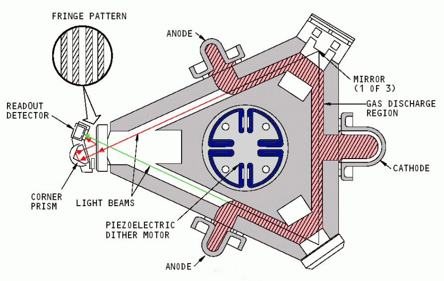
Diagram of a ring laser gyroscope.
Courtesy of Rogoway.
Applications of Ring Laser Gyroscopes
Inertial Navigation Systems (INS)
Ring laser gyroscopes have the advantage of not having any moving parts and thus, no friction. That is, it will not produce any extra drag for the machine it is incorporated into. Following, they are also lightweight and compact. In fact, as more R&D goes into creating new models of RLGs, they are getting smaller and smaller. For that reason, RLGs are perfect for integration in Inertial Navigation Systems. Inertial Navigation Systems are a technology that utilizes computers, accelerometers, and gyroscopes to calculate where it is in space. Accordingly INS are used to help ships, aircraft, and guided missiles through missions where GPS is not safe to use. Additionally, we will discuss the two different types of INS used in aeronautics navigation, stabilized platform INS and strap-down INS.
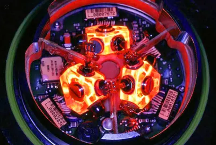
Ring laser gyroscope in usage for aircraft.
Courtesy of Rogoway.
Stabilized Platform INS
First, the stabilized platform INS consist of three accelerometers arranged to cover four different directions (North, South, East, West, or Up/Down). Additionally, several gyroscopes are used to maintain the platform’s alignment as the aircraft moves. These gyroscopes and accelerometers also output analogue data that can be integrated into velocity and direction information. Stabilized platforms may seem a good choice because its components are mounted and stay on well, but it has its cons.
For example, a lot of wear and tear occurs due to how things are mechanically mounted onto the platform. In addition, there are actually a lot of moving parts such as the gimbals that mount the gyros. Sometimes the gimbals end up in “Gimbal Lock” when two out of three gimbals align. As a consequence, the third gimbal’s movement will tamper with the movement of the other two and the gyroscope. A fourth gimbal can be added to the mix to prevent this locking event, although this would increase the overall cost.
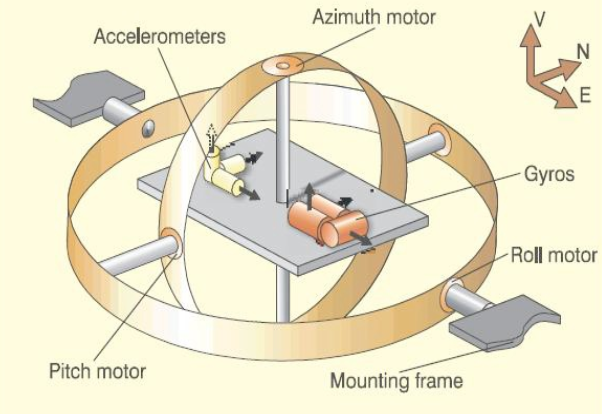
Diagram of example gimbaled inertial stabilized platform using mounts. Courtesy of Engineering 360.
Strap-Down INS
On the other hand we have the strap-down INS. In this system, the RLGs and accelerometers are fixed onto the frame of the aircraft with straps. Thus, no need for gimbals and the complex maintenance stabilized platforms do. The platform moves with the aircraft and the gyroscopes determine the rate of roll, pitch, and yaw. In addition, the accelerometers work just as they do with the stabilized platforms to give velocities and direction. One con of strap-downs is that they require higher precision gyroscopes as they cannot rely on gimbals. However, the overall cost of these INS platforms will actually be less than the stabilized ones because they do not require as much maintenance. They are also more lightweight and tend to be more compact, which is most ideal for efficient air vehicles.
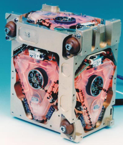
Marconi FIN3110 strapdown INS. Courtesy of Tampere University of Technology.
Missile Navigation
Modern day smart munition systems utilize INS and ring laser gyroscopes. Often, GPS is unavailable or unreliable in battlefields as GPS spoofing and tampering technologies are becoming more advanced. Guided munitions like missiles and artillery shells are also very weight sensitive as they must fly through the air long distances. That is why small RLGs and INS are perfect for battleground environments. Some specific examples that have started using INS systems are the Tomahawk cruise missile and M982 Excalibur. In particular, the M982 Excalibur is a 155mm guided round that experiences over 10,000 times the force of gravity during its journey.
To take on this challenge, Honeywell, one of the world’s top RLG producers, has utilized Micro Electro-Mechanical Systems (MEMS) to create an INS with RLGs (HG1930 Gun Hard IMU) that can withstand 20,000 times the force of gravity. Another example of a Honeywell INS is the HG1900 IMU and the HG1700. Both of these are under two pounds and utilized in guided bombs like the Paveway IV and Joint Direct Attack Munition (JDAM).
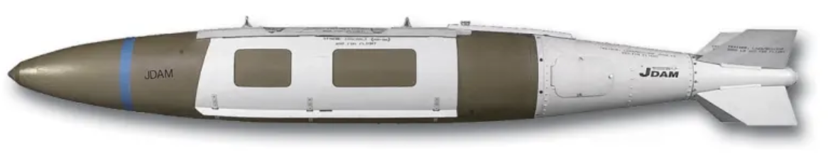
A Mk 84 bomb fitted with JDAM kit. Couresy of Wikipedia.
Conclusion
Ring laser gyroscopes are excellent choices for their low power, small size, and radiation independent operation. As more R&D is going into INS systems and GPS free devices, ring laser gyros are continually growing smaller and more convenient for air and spacecraft applications. Even among other optical gyroscopes like IFOGs, ring laser gyroscopes remain the first and main choice for applications requiring extremely high performance stability. As the military remains a large consumer of ring laser gyros, market projections will continue to steadily climb upward in the coming decades.
Good information about (RLG).
The brief description of the RLG, above, is not quite accurate and applies more to the Fiber-Optic Gyro (FOG). Here is an arguably better one:
The ring laser gyro (RLG) consists of a solid triangular or square block of glass with a hole drilled in it parallel to each edge. Mirrors are added at each corner, a mixture of Helium-Neon gases is added, and a stable laser cavity is formed by a suitable set of 3 or 4 mirrors. The conditions are chosen to allow two counter-rotating laser beams to be established – one clockwise (CW) and the other counter-clockwise (CCW). One of the mirrors is very slightly transmitting so that the CCW and CW beams can exit the laser cavity and then be mixed together in an interferometer that senses their relative phase.
If the RLG is stationary (not rotating) with respect to its central axis, the relative phase of the two beams is constant and the detector output is constant.
If the RLG is rotated about its central axis, the CW and CCW beams will experience a phase shift in the opposite direction. Since a ring laser gyro is an active device (as opposed to a passive fiber-optic gyro) this change is phase will force a corresponding change in the optical frequency of the counter-rotating beams. The result will be a beat in the audio band called the "Sagnac frequency" that is proportional to the rotation rate. This can be measured to very high accuracy by detecting the fringes when the CCW and CW beam are combined with optics similar to those used for homodyne metrology applications, which also provide directional information. In essence, the RLG is like a rotary encoder relative to a fixed inertial frame.
That's it in a nutshell, though in practice, it's not quite that simple.