The first radar systems were developed in 1935 by the German military. The term RADAR (Radio Detection And Ranging) was coined in 1940 by the U.S. navy. It was used during WWII to detect missiles, ships, aircraft, and terrain. Since then, more advanced technologies have emerge such as LiDAR and LADAR. LiDAR stands for Light Detection And Ranging, while LADAR stands for Laser Detection And Ranging. Some companies use these terms interchangeably. But a big distinction between these two systems are the size of their targets. LADAR is for bigger range surface sensing, like for mapping terrain or atmosphere. On the other hand, LiDAR is used for sensing small volume, concentrated targets (e.g. vehicles).
LiDAR and LADAR are remote sensing technologies that are much like regular RADAR. One similarity is in their function for measuring distances between objects and making 3-D maps of their targets. Some fundamental differences are that while radar uses Radio Frequency electromagnetic waves, LiDAR and LADAR systems use the visible and infrared sections of the light spectrum. Because the wavelengths of visible light are shorter than radio light, spectral resolution is much higher in LADAR than RADAR.
This makes LADAR a clear choice for modern 3-D mapping. In today’s article we will discuss the use of LADAR for two different 3-D direct detection active imaging technologies/techniques.
LADAR: 3-D Direct Detection Active Technologies
Scanning 3-D LADAR
Scanned laser radar technologies work by a laser that generates an optical (visible spectrum) signal pulse. This pulse is created such that it has low divergence. Then a scanner directs the pulse towards the targeted area and some of the incident light will be reflected/ back-scattered back to the device. This light is collected optically into a photosensitive component (like a photodiode). By way of the photosensitive component, the optical signal will turn into an electrical signal. Next, this signal is analyzed and filtered, and the round trip time it took to hit the target and come back can be found. Finally, with the round-trip time and the speed of light, the distance from sensor to the object can be calculated. For a more complete picture of a large area, the system will hit more targets and repeat the calculations.
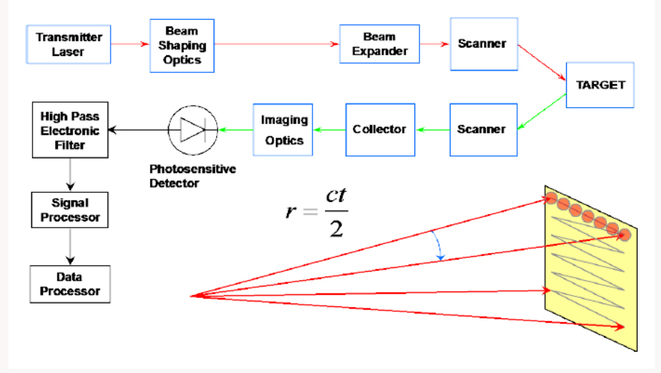
Block diagram of a typical bistatic, scanned 3-D imaging laser radar.
Courtesy of NAP.
The target data points are chosen in certain patterns, such as line or raster patterns. Some factors to take into consideration here are the angles of the signals, and the orientation of the sensor. From the data target pattern, these factors, and some trigonometric coordinate transformations, we can find the Cartesian coordinates of the targeted areas. This produces a high-resolution topographic map of the larger scanned area.
Flying Spot Systems
“Flying spot” scanned systems are one type of scanning 3-D radar technology. Their main purpose is for commercial airborne and ground-based topographic mapping. Most of these systems use just one photosensitive component to receive signals. That is because multiple detectors systems are expensive. They are not suitable for military usage because this technology requires several passes over the area, and typically need to be close to the target/ground. However, stealth is important in the military! Therefore, other methods must be used to create complete pictures more efficiently, such as in 3-D flash imaging.
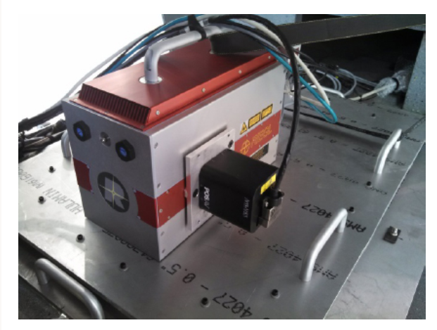
RIEGL LMS-Q780 Airborne Laser Scanner.
Courtesy of Riegl USA.
3-D Flash Imaging LADAR
The flash imaging method works by flooding the target area with light (many spots/points), and the reflected/ back-scattered light is collected by the receiver. The received signal is projected onto a 2-D array. Next, the 2-D map must be calculated into a 3-D map. Now a very similar process to the scanning 3-D radar systems occurs. To calculate the topographical map, factors such as the location and orientation of the sensors must be known. Finally, the 3-D map is born out of each calculated range.
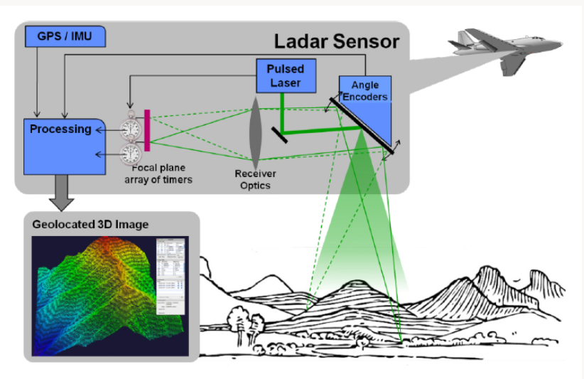
Diagram of 3-D flash imaging of a large area of terrain.
Courtesy of Lincoln Laboratory MIT, 2011.
Considerations for 3-D systems
Airplanes and moving vehicles typically take large area snapshots. As we know, motion causes image blur. Thus, it is best to take the image at a high frequency (less than 30 Hz)/ very short amount of time. Some other factors that are different from scanning systems are that multiple detectors must to used to receive signals. These detectors are put into arrays where factors such as spacing and phase affect the map calculations.
Additionally, the system receives a weaker signal because the returning energy signal is divided among multiple devices. In order to combat this weakness, high power light should be transmitted. Alternatively, the receivers should be tuned to be very sensitive. For example, this can be achieved by using Avalanche Photodiodes (APDs) or amplifiers to increase the power of the return signal. Further, Linear mode and Geiger mode amplifiers can also be used. First, the advantage of linear mode APD detectors is that the number of photons in the received signal has a linear relationship to the amplitude of the output signal. On the other hand, Geiger mode APD detectors have large gain even if the received signal is weak.
Conclusion
LADAR systems are advantageous to applications for precise detection of significant geographic areas. They allow high-resolution angle resolution and create highly data dense 3-D maps. Some emerging technologies in the works include multiple-input/ multiple-output (MIMO) imaging, femtosecond scale sources, and some in the quantum technologies domain. [1]
Did you know FindLight has a selection of Lasers for ranging and radar, including Eye-Safe Lasers?
Could LiDAR be used to detect and illuminate small airborne drones?
Yes, LiDAR (Light Detection and Ranging) can be used to detect and map the position of small airborne drones. The basic principle behind LiDAR is that it sends out pulses of light (usually laser) and measures the time it takes for the light to bounce back after hitting an object. By analyzing these reflected signals, LiDAR can create a high-resolution 3D map of the environment, including airborne objects like drones.
However, there are several factors to consider:
Range: LiDAR systems vary in range. For detecting small drones, a LiDAR with a long range would be beneficial, especially if trying to detect drones from a distance.
Resolution: To accurately detect and distinguish a small drone from other airborne objects or birds, the LiDAR system needs to have a high spatial resolution.
Interference: In an environment with many airborne particles (like dust, mist, or rain), the LiDAR’s efficiency might reduce, and the number of false positives might increase.
Cost: High-resolution, long-range LiDAR systems can be expensive.
Illumination: While LiDAR can "illuminate" a drone in the sense that it can detect and localize it, it does not make the drone visible to the human eye. If by "illuminate" you mean making it visible in the dark, then LiDAR wouldn’t serve that purpose. However, the data collected by LiDAR can be visualized on a computer to "see" the drone’s position in real-time.
Integration with Other Systems: For a more robust drone detection system, integrating LiDAR with other sensors like radar, cameras, or acoustic sensors could be advantageous. This multi-sensor approach can mitigate the limitations of each individual sensor.
Speed of Detection: Drones can move quickly, so the LiDAR system needs to be able to scan the environment rapidly to ensure it can track fast-moving drones.
To sum up, while LiDAR can certainly be used to detect small airborne drones, the effectiveness of the detection will depend on the specifics of the LiDAR system and the environment in which it’s being used. Integrating it with other sensors and systems can enhance its reliability and accuracy.